Thanks Amey,
Could you specify the exact model name of the ESP32 board you use?
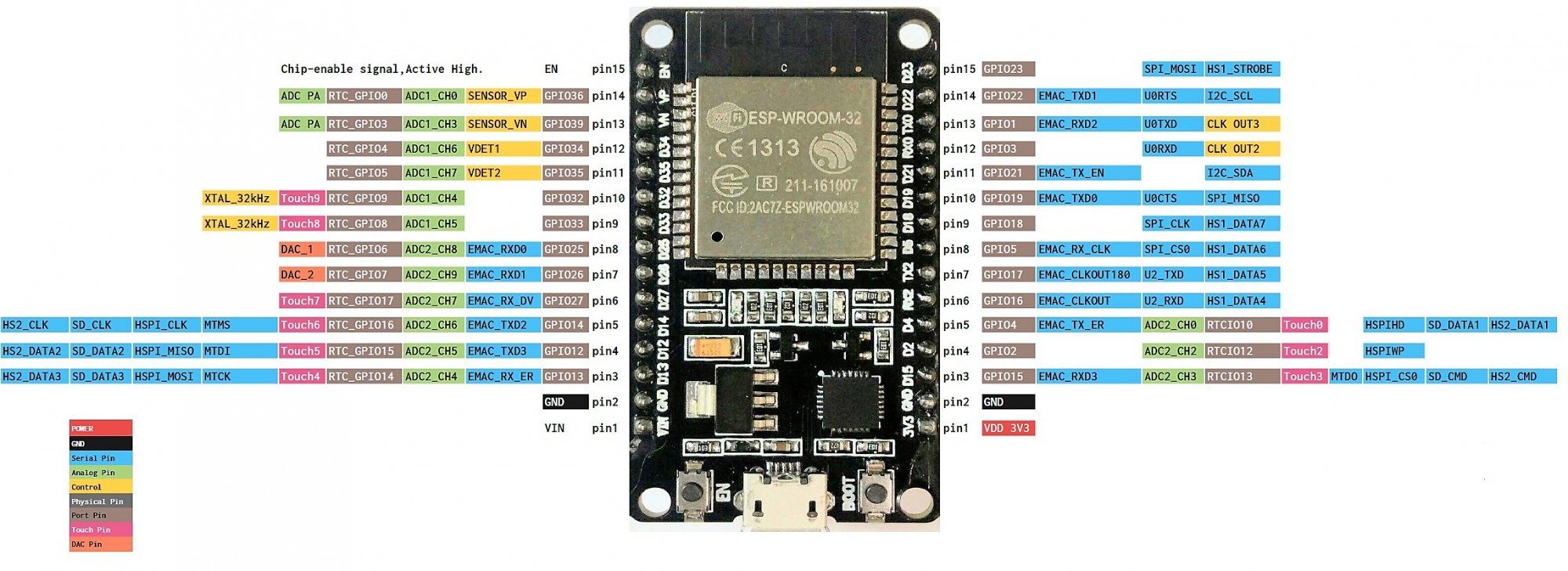
Does the PIN2 in your diagram mean GPIO2 in the image below?
Could you check the Arduino pin serial definition for those TX2 / RX2?
You’ll need to add the serial port and DIR pin Arduino definitions to the example code in order to make DYNAMIXEL2Arduino access the port.
If you have a logic analyzer or an oscilloscope, it will be very helpful to probe the PIN2 and the TX2 signals and see if there’s any DYNAMIXEL packet is transmitted.
Thanks!