How to implement a U2D2 on a PCB

Hello,

I am creating a robot that is controlled by an Arduino and Raspberry pi. My first thought was to use the Arduino to operate the dynamixel AX-12 (I have 4 of them that need to be controlled), but I realized that I won’t be able to send sensor data or receive commands while the Arduino is going through the planned trajectory. Therefore, I opted to control the dynamixels through the pi directly, which will allow things to run in parallel.

With this method, I clearly have to use the U2D2 However, after purchasing it, I cannot fit it within the enclosure of my robot. I really want to model the U2D2 on my custom-made PCB for the robot, but from my understanding, there are no schematics to go off of. Does anyone have any suggestions for how to control four dynamixel AX-12 servos using a raspberry pi by implementing your own circuitry?

One last question. Does the U2D2 have proprietary firmware installed on it?

Thanks in advance for any suggestions.

@Cory_Smith
Please have a look at this post for a proof of concept using the ttyAMA0 port of the RPi directly.

Have you managed to power your Dynamixels separately?

1 Like

@roboteer Thanks for the response. Through the method in that thread, the uart port on pi is used. However, what if I need 4 dynamixels?

If this method is functional for multiple, what is the point of the robotis U2D2? (I am quite new here, and I dont have a crazy amount of experience).

To answer your question about powering the dynamixels. I am going to power them through a 12V LiPo battery.

@Cory_Smith
Some more options to consider for your situation:

  1. Get a more “roomy” case for your RPi such as this one from OONO
    https://www.amazon.com/Semi-Enclosed-Enclosure-Raspberry-BeagleBone-Arduino/dp/B08PZCC562

  2. If your robot’s dynamic balance is not an issue (like for bipedal walking), and you have room to stick the U2D2 on the outside of your current RPi case, then see picture below for my solution when I had a similar issue:
    IMG_014632
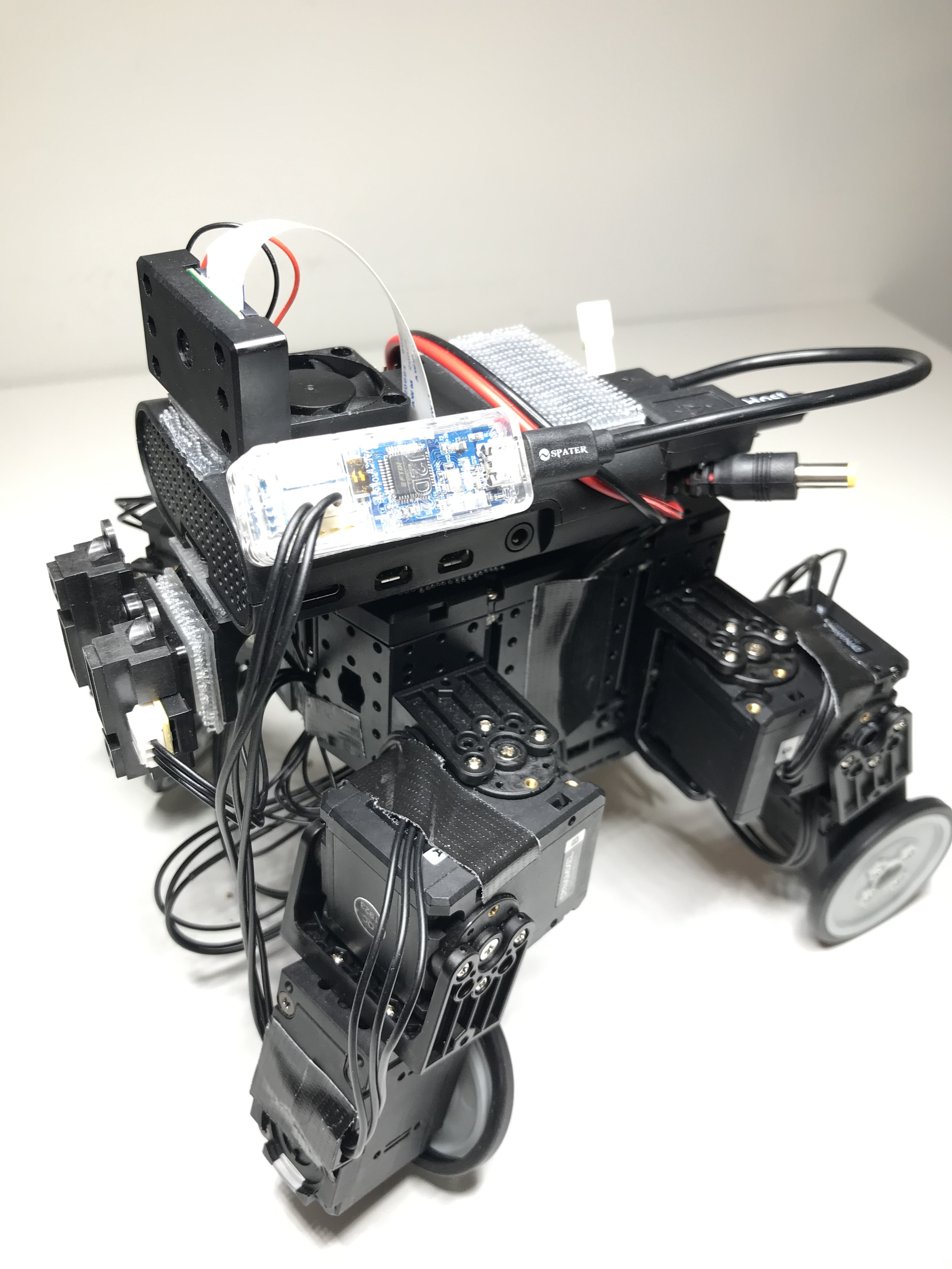
    where I just used 3M Dual-Lock tape https://www.amazon.com/Dual-Reclosable-Fastener-SJ3560-Clear/dp/B07QNMBB28.

  3. As you are using AX-12s you will need to buy one of these X3P convertible cables
    https://www.robotis.us/robot-cable-x3p-180mm-convertible-10pcs/
    to connect the U2D2 to your first AX-12, then you can daisy-chain the rest. If needed, this 3P-DXL hub can be handy https://www.robotis.us/3p-extension-pcb/ in case your 3P Dynamixel Cables do not run far enough.

1 Like

@Cory_Smith
First I think you need to understand just how a dydnamixel works.

A dynamixel servo is a complete package with a MCU, H-bridge and a number of sensors on the dynamixel. Each dynamixel has 3 pins(V+, GND and data). All the dynamixels on a project have all 3 pins chained together in parallel. How it works is each dynamixel has an ID number (address) and master controller (Pi or Ardunio in your case) sends a digital packet that is addressed to a persific ID with a comand of what it wants that dynamixel to do then the MCU on that dynamixel with that ID carries out the command.

The particular protocol that is used to send this data over the data pin is called UART half duplex. UART full duxplex is a very common protocol and most MCUs and RPi have built i hardware to use this communication protocol. Half duplex is less common and only some MCUs have builtin hardware half duplex UART, unfortunately both Ardunio and RPi don’t have hardware half duplex.

The U2D2 is a USB protocol to UART half duplex protocol converter.

UART full duplex can be converted to half duplex by joining the TX pin to the RX with a 4.7k pull up resistor. see Dynamixel on RPi on UART - YouTube

The dynamixels that I was using talk over UART half duplex at a baud rate of 1Mbps. RPi hardware UART is capable of these speeds but the standard OS setup has the UART input clock set to slow for these high speeds so you have to add init_uart_clock=16000000 to the config.txt file on the RPi then reboot to set the UART input clock to a fast enough speed

2 Likes

@Out_of_the_BOTS Wow thank you so much for a clear explanation! Therefore, I can simply use this technique of converting the full duplex to half duplex by connecting the Tx pin to the Rx through my PCB.

From what I understand then, the only point of the U2D2 is to use the usb port on raspberry pi.

@Out_of_the_BOTS I have another question. Why did this person follow the datasheet for converting the half-duplex by using the 74LS241. Dynamixel AX12 and the Raspberry Pi | Oppedijk.com

Everything I have read suggests this implementation rather than connecting the tx pin to the rx pin.

1 Like

@Cory_Smith

Seems that he converts the data from UART (Pin 0, 1) to half-duplex.

The basic concept of half-duplex is to do a data exchange using one data bus. While the data from TX port occupy the bus, RX port must be waiting otherwise, TX and RX data will be mixed up and corrupted anyway.

As DYNAMIXEL adapted half-duplex protocol (When TX data occupy the data bus, RX port must be waiting until TX end)

74LS241 is the three state buffer driver which can control the TX/RX bus line for data as the post insists.

The following is the simple circuit that explains how to control the data flow using three state buffer driver.

1 Like

@Cory_Smith

You will need a 4.7k pull up resistor because the TX pin idles high.

OK so the difference between a hlaf duplex and full duplex is that in full duplex there is 2 data lines with 1 line for each direction on communication, in half duplex both direction on communication happen on the same line so you can’t both transmit and receive at the same on time.

Any serial communication protocol can be either half duplex or full duplex not just UART for example I2C is a half duplex protocol. The circuit in that link is a very standard circuit for converting any serial protocol from full to half using 1 more control line to control the direction of communication. The timing to use this circuit with a dyanmixel is very critical as after the masters sends a data packet to the dynamixel the dynamixel sends a packet back and you would need to time the switching of directions very precisely.

If you use the TX pin as a pull up with a resistor then when ever the master transmits it will drive the data line through the resistor but when the master isn’t transmitting the TX pin idles high and holds the data line high but when the dynamixel wants to send a packet back it will drive the data line by pulling it low against the resistor so this means this direction switching will be done automatically

1 Like

@Cory_Smith

This is a better circuit for full duplex to half duplex converter, it works the same way as mine but protects the TX pin behind the transistors but this isn’t needed and I just cut out everything in the red circle

@Cory_Smith

This is a cut from the manual for the MCU that is on the dynamixel. So the dynamixel has a hardware half duplex UART. When it is in half duplex the TX pin and RX pin are connected internally and the TX pin is set to floating and RX pin to input floating, so that the master (RPi) can transmit then when the dynamixel wants to transmit it pulls the TX pin low to send.

@Out_of_the_BOTS Thank you so much!