Hi, I’m currently doing a project which requires controlling the servo (XC330-M288T) using an Arduino Nano 33 BLE. The operating mode of the servo is simple, it just needs to be controlled with the extended position control.
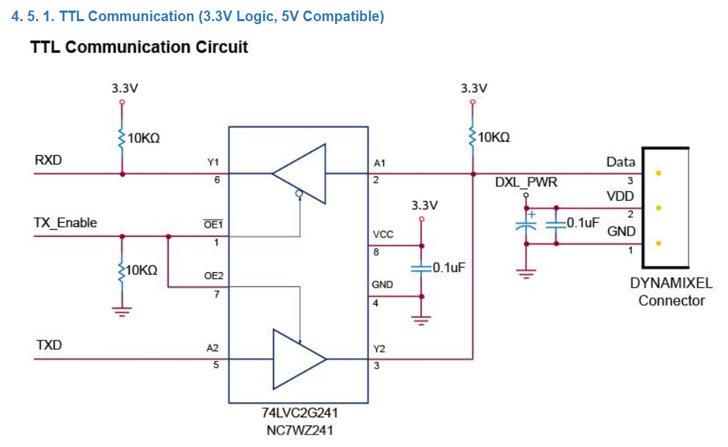
I understand that the servo uses TTL communication. I didn’t want to spend extra on buying the U2D2/ Dynamixel Shield/ Arduino MKR. Hence, I followed the recommended TTL communication circuit given in the datasheet, and connect the RXD & TXD to the Arduino’s RX/TX pin and TX_Enable to one of the Arduino’s I/O pin. And the servo is being powered by a LiPo battery.
After many tries, I still can’t configure the servo… I tried programming the example ‘ping’ from the Dynamixel2Arduino library and it gives an error. I also tried scanning for the servo with the Dynamixel Wizard 2.0 software, but the software did not find the servo.
Also, I’m using Visual Studio Code (Platform IO) to program the Arduino board.
Any help/guidance will be appreciated!
From a firmware newbie
The DYNAMIXEL2Arduino Library was developed for use with the shield on compatible boards.
I am unfamilar with the specifics of the nano, but a quick glance at a pinout shows that to try to adapt the library for use on that board and without the shield I think you will have to redefine at least the serial direction pin.
The Dynamixel2Arduino is specifically designed for ROBOTIS providing controller such as OpenCR 1.0 or other supportive controller. But I belive you can make your arduino board as same as long as building the TTL communication properly.
Before starting, I personally recommend testing your board to understand DYNAMIXEL and how to do comm. For the test purpose, when I use no library, but data sending only via UART, I simply made the code as below.
// Make sure this code is only for "Write". If you would like to get feedback from motor, halfduplex rule should be followed.

#include <SoftwareSerial.h>

SoftwareSerial mySerial(4,4); //Data Pin is on PIN 4

void setup(){

mySerial.begin(57600); // Set Baudrate accordingly.
pinMode(4,OUTPUT);

led_on_off(); // Check the Packet right transmitting if you don't get feedback from DYNAMIXEL

delay(10); //Give some interval between packets.

torque_en(); // Torque Enable should be implemented before starting the DYNAMIXEL

}

void torque_en(){

    mySerial.write(0xFF); // Header1

    mySerial.write(0xFF); // Header2

    mySerial.write(0xFD); // Header3

    mySerial.write((byte) 0x00); // Header4

    mySerial.write(0x01); // ID

    mySerial.write(0x06); // Leng(High)

    mySerial.write((byte) 0x00); // Leng(Low)

    mySerial.write(0x03); // Inst(Write)

    mySerial.write(0x40); // Param (Data Address)

    mySerial.write((byte) 0x00); // Param (Data)

    mySerial.write(0x01); // Param (Data)

    mySerial.write(0xDB); // CRC (Low)

    mySerial.write(0x66); // CRC (High)

}

void led_on_off(){

    mySerial.write(0xFF); // Header1

    mySerial.write(0xFF); // Header2

    mySerial.write(0xFD); // Header3

    mySerial.write((byte) 0x00); // Header4

    mySerial.write(0x01); // ID

    mySerial.write(0x06); // Leng(High)

    mySerial.write((byte) 0x00); // Leng(Low)

    mySerial.write(0x03); // Inst(Write)

    mySerial.write(0x41); // Param (Data Address)

    mySerial.write((byte) 0x00); // Param (Data)

    mySerial.write(0x01); // Param (Data)

    mySerial.write(0xCC); // CRC (Low)

    mySerial.write(0xE6); // CRC (High)

    delay(1000);

    mySerial.write(0xFF); // Header1

    mySerial.write(0xFF); // Header2

    mySerial.write(0xFD); // Header3

    mySerial.write((byte) 0x00); // Header4

    mySerial.write(0x01); // ID

    mySerial.write(0x06); // Leng(High)

    mySerial.write((byte) 0x00); // Leng(Low)

    mySerial.write(0x03); // Inst(Write)

    mySerial.write(0x41); // Param (Data Address)

    mySerial.write((byte) 0x00); // Param (Data)

    mySerial.write((byte) 0x00); // Param (Data)

    mySerial.write(0xC9); // CRC (Low)

    mySerial.write(0x66); // CRC (High)

}

void goal_pos_1024(){

    mySerial.write(0xFF); // Header1

    mySerial.write(0xFF); // Header2

    mySerial.write(0xFD); // Header3

    mySerial.write((byte) 0x00); // Header4

    mySerial.write(0x01); // ID

    mySerial.write(0x09); // Leng(High)

    mySerial.write((byte) 0x00); // Leng(Low)

    mySerial.write(0x03); // Inst(Write)

    mySerial.write(0x74); // Param (Data Address)

    mySerial.write((byte) 0x00); // Param (Data)

    mySerial.write((byte) 0x00); // Param (Data)

    mySerial.write(0x04); // Param (Data)

    mySerial.write((byte) 0x00); // Param (Data)

    mySerial.write((byte) 0x00); // Param (Data)

    mySerial.write(0xB2); // CRC (Low)

    mySerial.write(0x89); // CRC (High)
}

void goal_pos_2048(){

    mySerial.write(0xFF); // Header1

    mySerial.write(0xFF); // Header2

    mySerial.write(0xFD); // Header3

    mySerial.write((byte) 0x00); // Header4

    mySerial.write(0x01); // ID

    mySerial.write(0x09); // Leng(High)

    mySerial.write((byte) 0x00); // Leng(Low)

    mySerial.write(0x03); // Inst(Write)

    mySerial.write(0x74); // Param (Data Address)

    mySerial.write((byte) 0x00); // Param (Data)

    mySerial.write((byte) 0x00); // Param (Data)

    mySerial.write(0x08); // Param (Data)

    mySerial.write((byte) 0x00); // Param (Data)

    mySerial.write((byte) 0x00); // Param (Data)

    mySerial.write(0x42); // CRC (Low)

    mySerial.write(0x89); // CRC (High)

}

void loop(){

    delay(750); // Give it a time while pysically moving.

    goal_pos_1024(); // Move 1024 (90 deg)

    delay(750); // Give it a time while pysically moving.

    goal_pos_2048(); // Move 1024 (180 deg)
}
My setup as following:
Digital Pin 4 is assigned as a software serial pins instead of using 0,1
I highly recommend using hardware serial pins (0,1) as you can perform quicker packet transmission and higher baudrates support (thanks to UART converter built in a chip)
Note that you can not get feedback from DYNAMIXEL by this setup. DYNAMIXEL should communicate with its master device under the Half-Duplex rule (While TX pin is under control, RX pin must wait until TX is done), therefore you should build the buffer enable (Triple State buffer) as below (or do it programmatically using software serial library. Some of the users have achieved it).
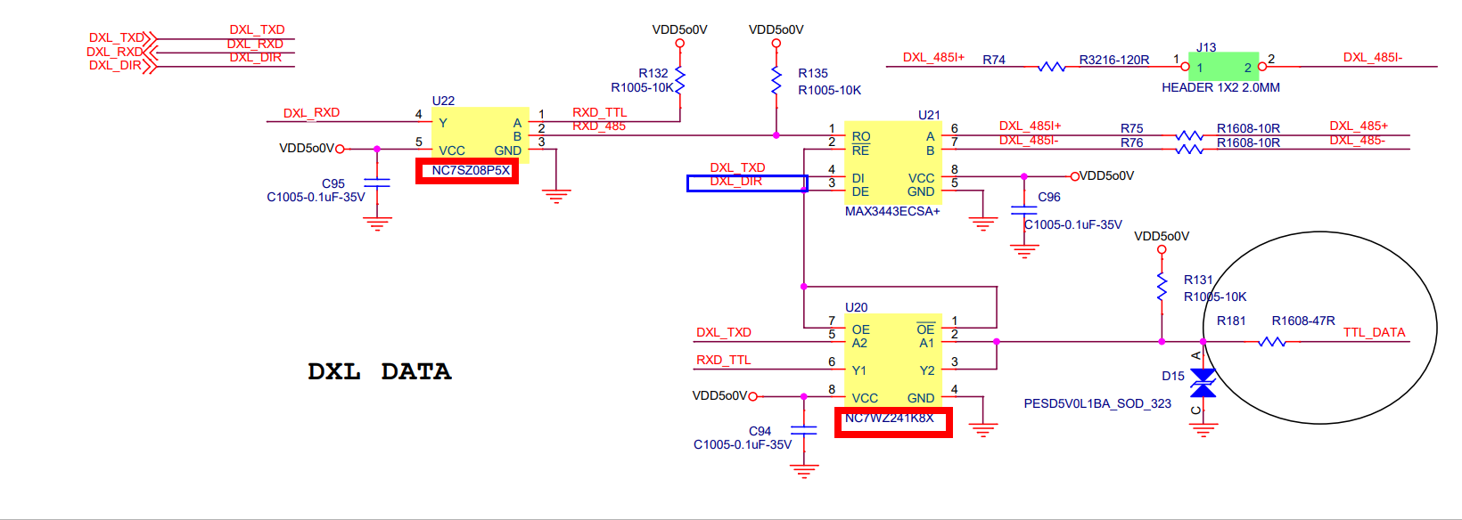
I found the useful resource regarding the use of TTL & RS485 data flow at OpenCR 1.0 circuit at ROBOTIS Official Github. Although, the DXL data (TX/RX) are generated by the MCU of the controller, I believe you can just use, from Arduino ,TX(1)/RX(0), and DXL_DIR(2) pins that enables / disables the TX/RX direction for half-duplex.
Thank you for your tips! Unfortunately, Arduino Nano 33 BLE doesn’t support the SoftwareSerial library… Will I still be able to do it by extracting the functions from the library?
I’m currently doing the setup on breadboard but I’ll need to build it to a PCB in the future, how will I need to go about disconnecting TX/RX pins when uploading if I’m using the PCB?
I have little experience with firmware development, hence a bit stuck in the coding part where I don’t know where to start on. I was hoping that there’s a library that I can call the function and use the servo, but apparently, the majority of the libraries don’t support Arduino Nano 33 BLE
A summary of what I understand so far from online is that there are 2 ways to do TTL communication.
Method 1- Hardware Serial
Need a tri-state buffer chip and connect RX & TX (I assumed that this is the recommended circuit in the datasheet)
As the software serial is not reliable at higher baudrates (Might be over 57600 bps), I recommend going for Hardware Serial with TTL transiver and achieve a half duplex.
If it’s difficult, I was told that there is a transiver that automatically do the half dulex.
Note that Arduino Nano BLE does’t seems to me that support 5V tolearnace to I/O pins according to its datasheet
Arduino Nano 33 BLE only supports 3.3V I/Os and is NOT 5V tolerant so please make sure you are not directly connecting 5V signals to this board or it will be damaged.
There fore, you may want to give 3.3V Pull-up to the RX , not 5V.
Note: I’ve found another schmetic for you which is designed for DYNAMIXEL MKR Shield that pulls 3.3V to the VCC of RX, and this would more fits in your board. See below.
Thank you for your advice!
about the hardware serial schematic, I’m not sure why the Dynamixel MKR Shield uses two of the buffer chips whereas the recommended TTL communication circuit from the datasheet only uses one (XC330-M288-T) - this is my current hardware setup [my current concern is the firmware setup].
Seems that MKR shield use two single buffer drivers with Inverting enable or enable pin. It can be used for either TX/RX depending on data line.
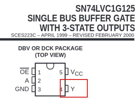
74LVC1G125: Signle buffer driver allow one output only.
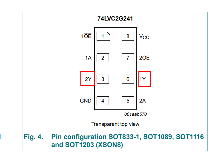
The 74LVC2G241 (used in DYNAMIXEL TTL driver you attatched) is a dual buffer driver which contains two 3-state output (Containing both Not gate Enable and Enabl unlike the other chip above.)
74LVC2G241: Dual output allows two outputs along the OE and OE^ pins
Hi,
Just wondering when connecting the Arduino’s Rx & Tx pins to the RXD (Y1) TXD (A2) of the buffer chips, is it (Rx - TXD/ Tx-RXD) or (Rx-RXD/Tx-TxD)?
Also, I understand that the dynamixel2arduino library is for shield on compatible boards. Since, I’ve implemented the half-duplex hardware so I assume that I don’t need the software serial library anymore and able to used the dynamixel2arduino library, I just redefined the DXL_DIR_PIN to one of the I/O Pin and tried running the sample code to ‘scan_dynamixel’ to find the servo but still unable to find the servo.
You do not have to go Software serial if you don’t need additional Serial port. The software sererial library for DYNAMIXEL Shield (Interfacing UNO) is mainly used for reading serial data through UART. But as the DYNAMIXEL Shield and UNO shares the 0,1 ports, the serial data should be received through other ports using the software serial ports. Otherwise, you do not have to I guess.
Thank you!
I think the Arduino nano 33 BLE have the same case as the UNO board (Serial - Arduino Reference), shares the same serial ports that’s why I couldn’t find the servo.
If I implemented software serial, do I still need the hardware buffer? (I guess I dont need hardware buffer right?)
As there’s no software serial library that supports Arduino Nano, are there ways around for having additional serial ports and not implementing software serial?
I’ve seen some of user achieved Half-duplex using Software Serial, but there is some limitation which I don’t remember
Sending a Ping process is as follows you may know well.
Master TX (Ping Instruction) >>> DYNAMIXEL (DXL Pin for TX mode)
DYNAMIXEL (Return Status Packet) >>> Master RX. (DXL Pin for RX mode)
I am not sure how software serial works here, but check the DXL_DIR_PIN which should properly activate the TX/RX direction while communicating. As mentioned, Software Serial does not provide high bps, use the low baudrate either.