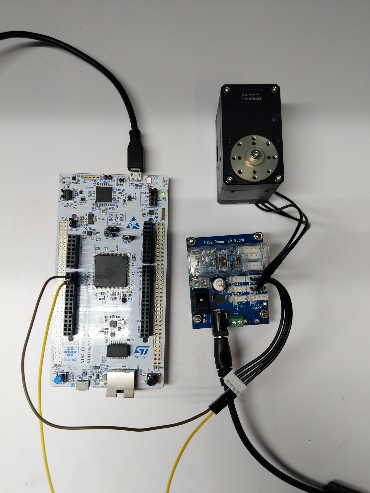
Hello! I am looking for help working with the XM540-W270-R actuator. I am trying to control it via a NUCLEO-H743ZI2 development board. I have 2 basic objectives: 1) be able to write various position 2) be able to read the data off of the servo. I have gone through many of the Robotis references and believe I have constructed the required packets to be sent to the servo correctly over UART but when transmitted and received I get nothing. I am unsure where my error is whether it be physical or software and am very novice to this so please bear with me. I am using CubeIDE on the development board and have wired a UART Rx and Tx line to the rs485 socket on the dynamixel starter kit. I am unable to just use the SDK directly as the development board does not have a windows, Linux, or Apple based operating system. If I have left out any key details please call me out and I’ll be happy to provide what I can. Thank you!
Edit: Ok so here are some pictures to clarify more on what the setup and code (written in C) look like:
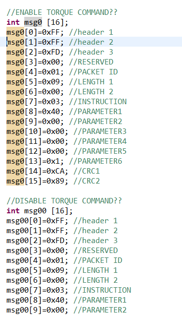
Figure 1: This is an example of how I’ve constructed the packets. What’s shown is just the enable and part of the disable torque commands but I also have a status packet, temperature read packet, and goal position packet. I’ve initialized them as int arrays and used the hex format.
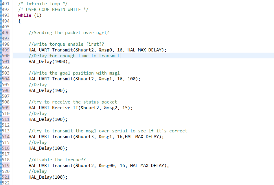
Figure 2: this is my procedure and how I am transmitting over the UART lines. I have used an oscilloscope to see that these lines are transmitting and they are but I cannot say definitively that it is correct. Same goes for the actual sequence of events.
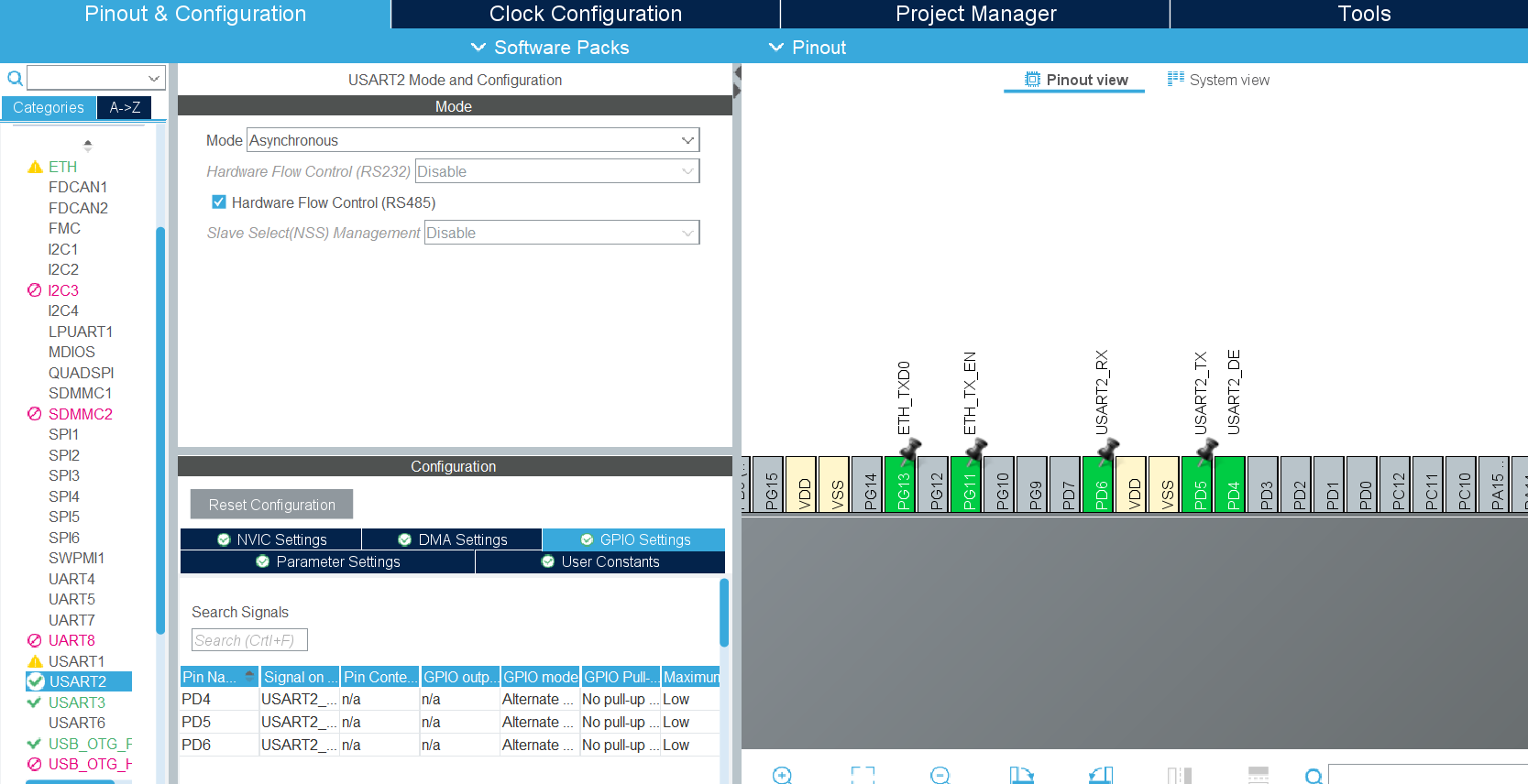
Figure 3: This is CubeMX where I have initialized the tx and rx line with rs485 hardware flow control. If there is anything not in the picture that you need me to expand on I’m happy to do so.
Hello @Maguiler, thank you for your post and welcome to our Community Page! This sounds like a more specific question related to the capabilities of the NUCLEO-H743Z12 board so to begin with, allow me to bring in a few members from our page who may be able to assist further. @willson, @Yogurt_Man, @roboteer, would you have any information or experience regarding programming for a DYNAMIXEL unit controlled in a similar embedded environment?
The UART port on the U2D2 doesn’t convert the UART to RS-485 or TTL.
It is translating signals between the USB and the UART for (mostly) debugging purpose.
In order to send the RS-485 signal, you should use the UART - RS-485 converter.
First of all I haven’t used the STMH7 line and mainly play with the much simpler easier to use STMF4 line of MCUs.
Second I haven’t used RS485 but have used UART plenty of times before. I didn’t even know that STMH7 has native RS485
First thing I always try with serial coms is swap the 2 pins the other way around in-case wiring is backwards. I haven’t used the starter board either but the 2 data pins for the RS485 pins should be the ones with the little resistor between them. Beaware the other pins on the connector will be the full votage for the dynamixel servo so if you connect the data pins to full voltage you will damage your STMH7 board.
Second thing I always check with Asynchronous serial com is the baud rate.
If you have a logic analyzer then attach it to the data lines to see if data is being sent. If you don’t have an logic analyzer then attach 2 LEDs between the 2 lines setup each LED in oppsite polarity with the correct sized resistor so you can see if they flash so you know data is being sent.
Another thing to note is when receiving UART I usually setup a DMA transfer to automatically move the data from the UART input register into a buffer because the hardware UART peripheral will only store 1 byte in the input register and will just throw away any further received bytes until that byte is read and the flag is cleared. If your not goin to use DMA then try removing the delay you have between the sending and the recieving so that as soon as it finishes sending then it starts to receive and clear the 1 byte input register so that it can receive the next byte.
Something else that I have just noticed. You have made an array of 32 bit int rather than an array of array of 8 bit unsigned bytes. You will need to change all your arrays to correct data type
Thank you for the assistance! I changed my array initialization, my packet, and my circuit slightly and that seemed to let me write position and move the servo. I still have more debugging to do but this helped significantly. I don’t have a logic analyzer but I have an oscilloscope, not sure if they have the same functionality but I’ll do some research. Still working on it but I’ll update when I can!
If your having trouble reading back it will help to understand how the hardware UART peripheral works.
When the UART is reading what it does is when it receives a byte it puts the recived byte in the output register then it sets a flag in the flag register to let you know there is a byte ready to read. It won’t read any more bytes until the flag is cleared then it will read the next byte that comes after the flag as cleared and put it in to the output register then set the flag again.
So you basically have 3 options.
poll the flags register and when the flags is set then use your HAL_UART_Recive() function to read the incoming bytes. You can basiclly modify you code so that you do this instead of the HAL_Delay() your using so it delays untill the flag is set rather than delay a set amount of time.
You can setup a hardware interrupt that triggers when this UART flag is set that then uses HAL_UART_recive() fuction
You setup a DMA transfer that will trigger when the UART flag is set and transfer the byte to a buffer and then clear the flag. You can setup the DMA as a circular buffer than increments with each byte.
Please note that the UART and the RS485 use different physical layers.
D+ or D- of the RS485 layer doesn’t represent TX or RX, but they are just an inverted signal to each other and they are combined in the RS485 IC of DYNAMIXEL to be interpreted as a half duplex RS485 signal.
Without a proper implementation for RS485 circuit on your Nucleo board, communication with DYNAMIXEL cannot be guaranteed.
It is my understanding that the STM32H7 has a native RS485 hardware peripheral that puts out an inverted signal on the TX and RX pins unlike the STM32F4 which only has UART hardware peripheral.