Anteater Dynamics: 7 Degree of Freedom Robot, UC Irvine

Hello everyone!

My name is Rogel Aguilar and I am with the Anteater Dynamics team here at the University of California, Irvine. Our school has partnered with ROBOTIS for a senior design project that aims to create a low-cost 7 degree-of-freedom robot using Dynamixel actuators. Our team will be sharing weekly progress updates.

Please check out out GitHub for more detailed updates (code, images, CAD, etc.)

Feb. 06 2025 Updates:

Mechanical
This past week our mechanical team has refined the conceptual CAD of the robotic arm into a functioning assembly with Dynamixel actuators.

Electrical
Our electrical team has been compiling an initial BOM for all of the components of our robot.

Software
Our software team has been exploring different simulation software and familiarizing themselves with ROS and Gazebo.

Next Week’s Goals

  • Begin FEA simulations of our CAD model.
  • Continue work on the BOM.
  • Decide and research what type of controller our robot will use.
3 Likes

Hello Everyone!

This is our second update for Anteater Dynamics. These past two weeks saw significant progress in the concept generation stage of our robotic arm and the finalization of the BOM.

Mechanical
These past two weeks our Mechanical Team has further refined the CAD of our robotic arm, and has begun FEA simulations to ensure the durability of our chosen designs. Additionally the load-cell for our end-effector finalized

Electrical
Our electrical team has completed our initial BOM for the components of our robotic arm. They have also began work on the wiring diagram.

Software
Our software team has agreed to use an OpenRB-150 micro-controller for a Proof-of-Concept (Poc) and now we are exploring different options on how to control the full-scale project.

Please check out out GitHub for more details on our FEA simulations and screenshots of our CAD assembly.

We look forward to sharing our progress next week!

Next Week’s Goals

  • Continue refining the design of the linkage arm
  • Begin manufacturing of the end-effector components
  • Begin writing the code for the 4 DOF PoC
1 Like

Hello Everyone!

This is the third update from Anteater Dynamics. Our team is in the final stages of our initial concept generation and planning . This past week, extensive analyses was done on various components of our preliminary design, finalizing many of our design choices. Our Proof-of-Concept model has been revised as well. Rather than a full 4 DOF robotic arm with an end-effector, our team has decided to create two different models. Our fist model will aim to test the effectiveness of the end-effector’s grip with the load-cell feedback. The second model will aim to verify the movement of a 4 DOF robotic arm linkage.

Mechanical
This past week our mechanical team has finalized the design of our arm linkages. The results were verified through FEA. Additionally, manufacturing of the end-effector model has been delayed to improve the printability of the components. More details about the FEA can be seen on our GitHub.

Electrical
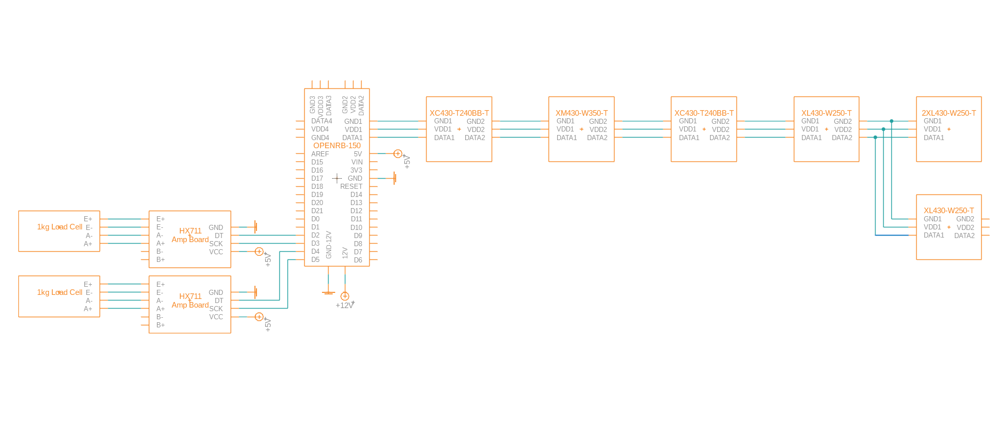
The electrical team has completed the initial wiring diagram (shown below) for our PoC model.

Additionally, the electrical team assisted the mechanical team on performing FEA to ensure the strength of our custom bracket for our end-effector.

Software
Our software team has created a rough flowchart of the pseudocode for the 4 DOF PoC model.


Additionally the team conducted analyses on which controller would be the best option given the scope of our project. Our analyses concluded that direct control via PC and the U2D2 communication converter would be best for our final 7 DOF end-goal, while the OpenRB-150 would be best for our Proof-of-Concept model.

Next Week’s Goals

  • Refine and improve the layout of the robotic arm base.
  • Begin manufacturing the end-effector model/prototype.
  • Set up calibration testing for load cells once in hand.
  • Converting the pseudocode into Arduino sketches

Some of the challenges we anticipate will be errors or malfunctions in the printing of our end-effector components. Additionally we expect to troubleshoot and debug our code during the set up of the calibration testing for the load cell.

We look forward to hopefully sharing our first physical models next week!

Hello everybody!

This is the fourth update from Anteater Dynamics. Significant progress has been made since our last update.

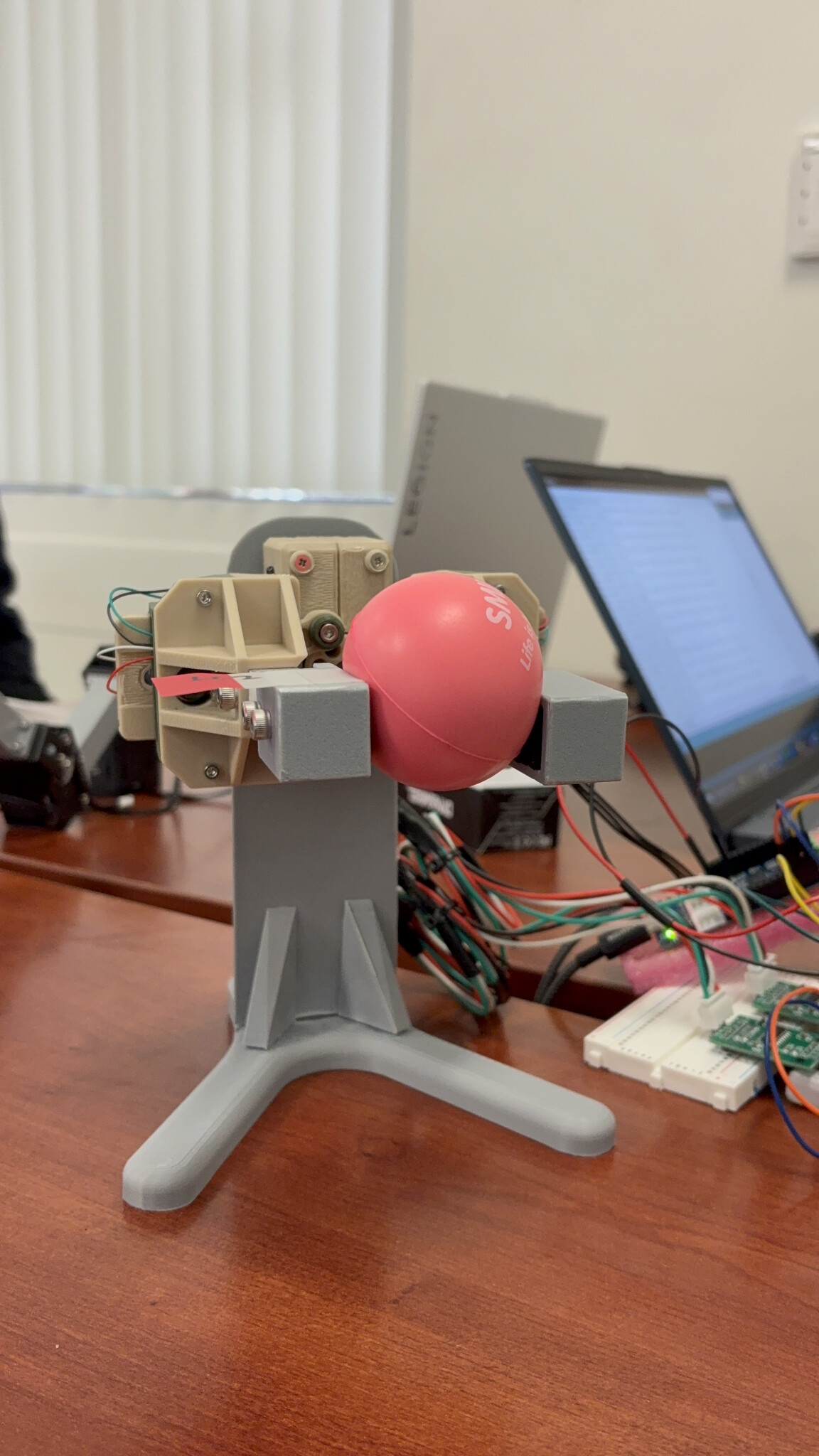
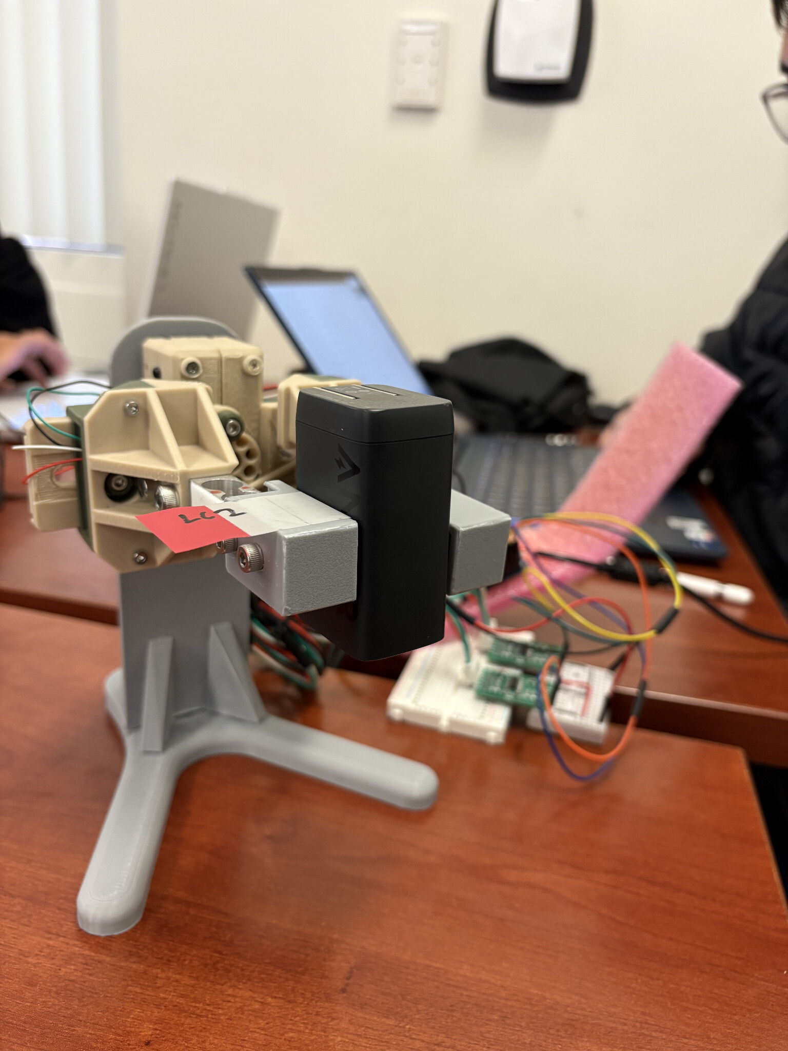
The team presented the PoC models at our school’s annual design review. Below are images of the end-effector model holding and gripping two objects.

While not shown in the picture, the end-effector was successful in sensing how much force was being exerted on the object via feedback from the load-cells. Unfortunately, this model was not able to identify whether it was gripping a “soft” or “hard” object, and is something our team is actively trying to solve.

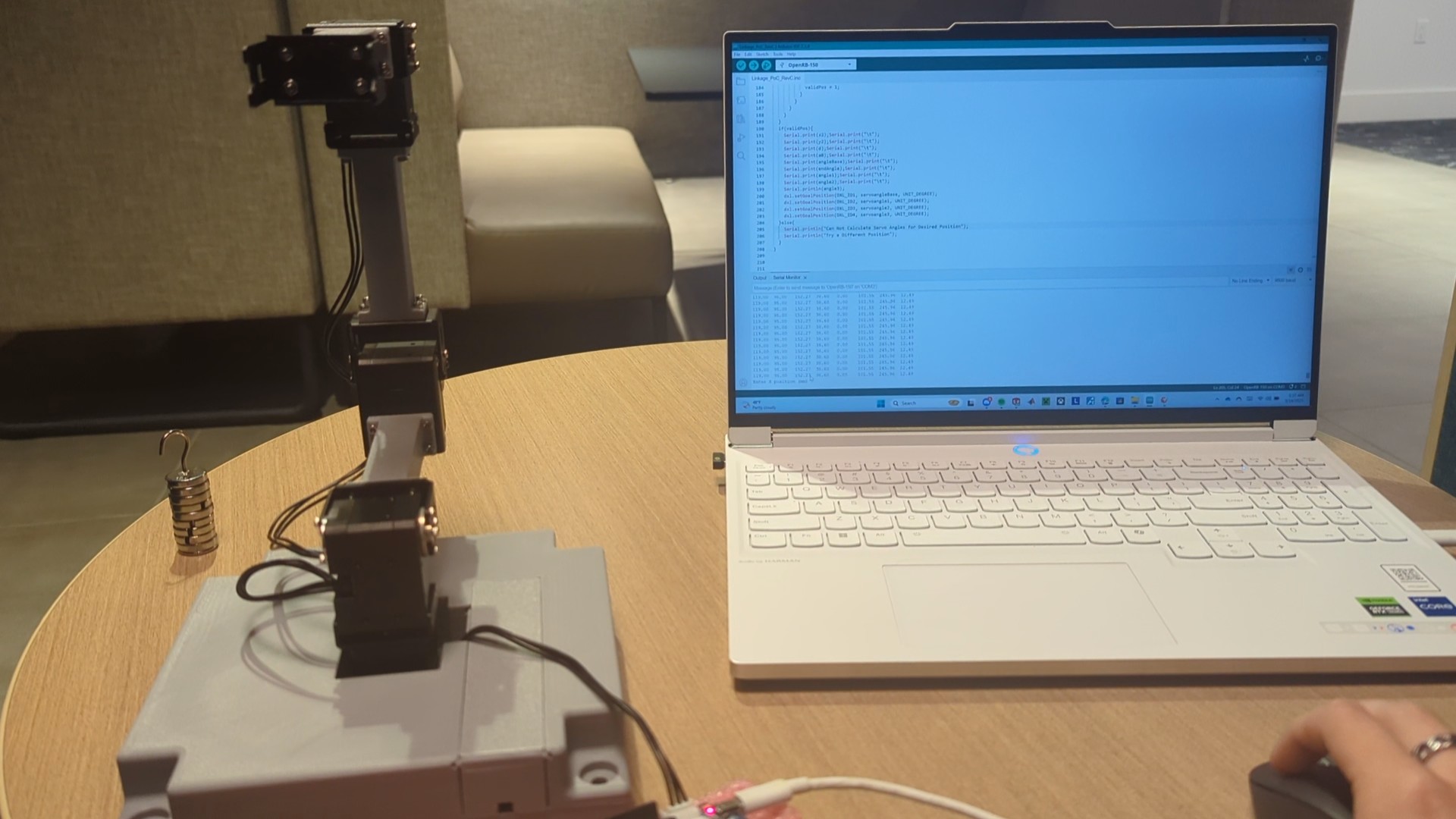
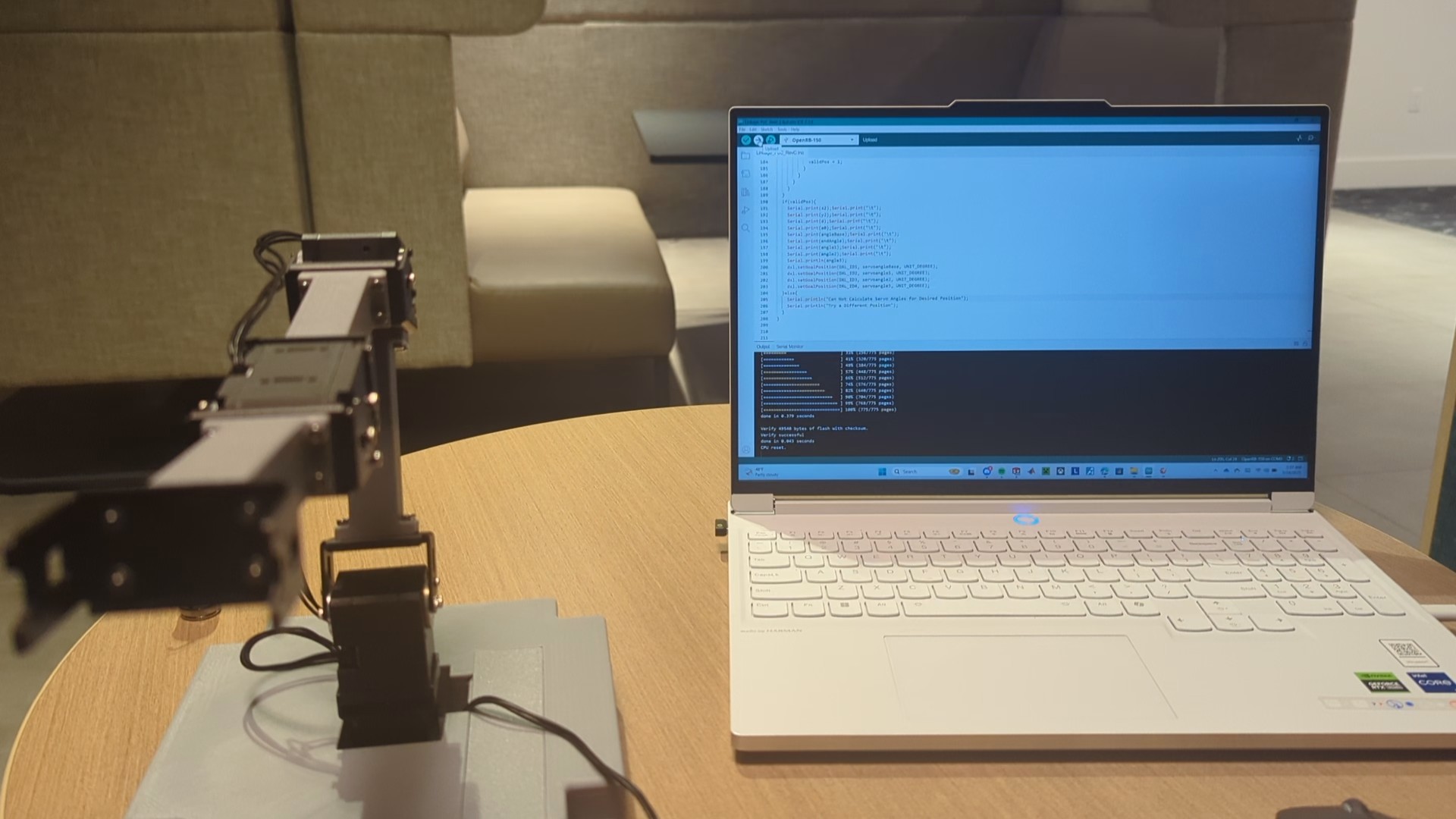
Below are images of our robotic arm linkage in different poses:


The linkage arm was successful in maintaining its position after having an added load attached to its end. Some issues were noted, including the need for better cable management between the different Dynamixels. For example, the wires near the base wrapped around the linkage, preventing our robotic arm linkage from freely rotating 360 degrees about the base. One of our goals for the final prototype is internal wiring as well as adding shrouds to reduce the amount of exposed wires.

Mechanical
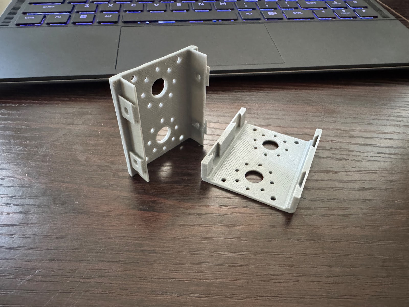
Our mechanical team has been working on new components for the final prototype. Attached below are images of the joint shrouds mentioned earlier to reduce wire exposure. The first iterations tried to use a snap fit model to attach to the servos, but given the constraints of FDM 3D-printing and its loose tolerances, we ultimately decided to use fasteners to attach the shrouds.

Additionally, work has been done to improve the design of the custom-made wrist bracket attaching the end-effector to the rest of the arm linkage. On the left is the model of an off-the-shelf aluminum bracket. We wanted to avoid any stress or issues with cantilevering, given that our bracket will be 3D Printed, hence the uniform design.

Software
Our software team is currently working on developing a kinematic model for our complete 7DOF prototype, as well as further developing the logic behind the load-cells sensor feedback. Currently, the end-effector is successful at reading the force exerted on the object it is gripping, but cannot distinguish whether or not it is sensing a “hard” or a “soft” object.

Next Week’s Goals

  • Continue research and development for end-effector test objects.
  • Update the base design to ensure proper packaging of the Open-RB150 controller
  • Continue assembly and manufacturing of the finalized components.
  • Continued development of the forward kinematics model
  • Continued troubleshooting and developing of sensor logic for the load cells.
  • Begin integration of the end-effector and arm-linkage sub-systems.

Some of the challenges we face are issues with tolerancing and fitting of the manufactured parts. On the software side, we expect further challenges in finding different methods of identifying soft/hard objects, as well as fully implementing the forward kinematics model to understand the robot’s geometry.
1 Like