Hello all,
I am new to this field, and I am working on a chess-playing robot arm. I’m hoping to get your advice on the best operating mode for achieving the results I want.
I originally tried to use velocity control mode, where I was modifying the target velocity as the servo approached the target position. I thought this might be better suited for slow-and-steady motion compared to a PID loop with position mode. But I noticed the velocity control mode was struggling to maintain a constant velocity, which makes sense given the variable torque produced by the orientation of the arm and gravity.
I’m now thinking that to have really good results, I’ll need to do serious motion planning- setting a target path, calculating angles, velocities, and accelerations along it, and using the joint space dynamics equation to determine the torque to apply at each point. Do you think this is the best approach? If there’s an easier way that’ll save time, I’m all ears.
If it is the best approach, how should I decide between current and PWM control mode? I thought that there is a direct relationship between current and torque, so I should use the current mode. Thank you.
New users can’t upload pics unfortunately or I’d show some pics of the arm and the velocity graph.
Thanks,
Matthew
The approach that you mentioned in your post would certainly be the most performant solution to this particular application, especially if combined with PWM mode for direct output control so you can implement the motions generated by your motion planning system.
However, this is also going to be a bit more complicated than is probably strictly necessary for a chess playing robot that doesn’t necessarily need to move particularly quickly or with low latency in trajectory updates. A simpler overall solution would be to have your motion planner just output desired joint angles for each actuator, and update them simultaneously in a position based mode to put together a bit of a simpler system.
1 Like
Thank you for the response. In a position based mode, the torque needed to get to a position is going to be dependent on the orientation of the arm (because of gravity), is that correct? Would this mean mean dynamically changing PID parameters as it moves?
The DYNAMIXEL’s motor controller will handle the basic motion generation pretty much transparently in position based modes, but you would be able to get more control with properly tuned PID values, although you shouldn’t need to change them too much at runtime unless you need very high precision or a specific movement behavior.
1 Like
Sorry I’m still unclear. Are you saying you think position control mode will suffice? I’m just concerned because when the arm is fully extended to reach a piece on the other side of the board, the amount of torque needed to accelerate the ‘shoulder’ is going to be a lot more than when the end effector is close to the base. Am I able to change the PID parameters without disabling torque? Thank you.
To clarify, I think position control mode would suffice. The amount of torque will differ depending on the current orientation of the joints, but the DYNAMIXEL’s trajectory generator can compensate for that on it’s own in a time based trajectory generation mode, unless you need direct control over it for a particular reason in your application.
1 Like
I’m just sure what a time based trajectory generation mode is. Is it different than the operating modes (e.g. position control mode)? Thank you
You can watch this YouTube video for a demo of several ways to do Position Control with X-series of actuators:
There is actually a Time-Based Position Control mode that you can read about in this free Kindle Sample - see Sub-Section 2.1.4:
https://www.amazon.com/Projects-Guide-ROBOTIS-ENGINEER-Combined-ebook/dp/B09KQCH2FV
This book uses TASK, MOTION, and Dynamixel SDK in Python and C++. Eventually you will need to learn about SyncWrite also for your project.
If you are thinking about using Arduino, then this book is more appropriate:
https://www.amazon.com/Using-ARDUINO-ROBOTIS-Systems-Ngoc-ebook/dp/B0BPXGQ6YX
1 Like
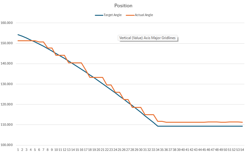
@ROBOTISUSA and @roboteer, both of your advice have been very helpful, and I got the elbow moving smoothly to the target position. Jonathon was right, the servo’s motion planning seems to work very well despite the changing torque due to gravity. I did some testing and originally was seeing if I could set a new target position every 0.05 seconds to make it follow a ‘path’, but it wasn’t very smooth. It worked a lot better to just set the position of the end destination as well as the profile velocity. I wouldn’t have been aware of the profile velocity functionality if you hadn’t shown me the video, roboteer. Thank you.
There does seem to be a consistent issue of being off by a few degrees at the end of the movement, I’m not sure how much of an issue that’ll actually be. Do you think that’s just a matter of tuning PID parameters? I messed with them a little bit but didn’t see an improvement.
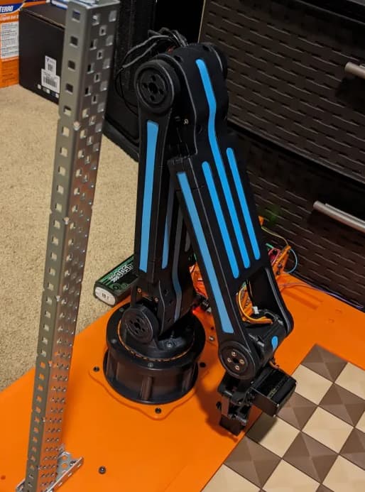
Here’s a pic of the arm.
That is mechanical backlash from the spur gear trains. There is nothing much that we can do from the user’s end. Unless you have a budget that allows the use of high end servos that cost in thousands of dollars for ONE.
You can also try this post
Vibrating/adjusting motor when in position - Technical Support - ROBOTIS
Maybe I’ll add a few degrees to the target position to compensate?
The backlash happens at any Goal Position value and it is at random too. You can help some by using the trapezoidal profile, ie Profile Acceleration should not be kept at zero value.
Some additional PID tuning (specifically adjusting the I Gains) will likely also bring some improvements, but as Roboteer said, there will always be a little inaccuracy due to the mechanical slop from the gears.