How to control multi AX-12A servo motors by using Dynamixel shield

DYNAMIXEL Actuator

Dynamixel AX-12A

Issue Description

Hello, I am using three AX-12A servo motors in my project. However, I am not sure how to control it by using Dynamixel shield and the example code. I can confirm that Dynamixel Wizard 2.0 can scan and find all three motors. And I can control each of them by using the example code (Examples—>DYNAMIXELShield—>Basic—>Position Mode). However, I am not sure how to control them together. Could you please give me some advice?

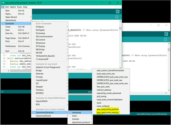
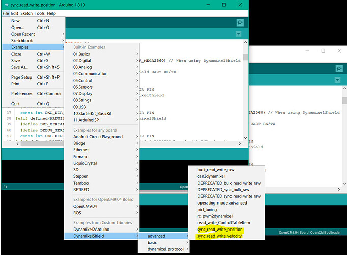
You should try the Sync_Read_Write examples in the Advanced folder for either Dynamixel2Arduino or DynamixelShield libraries.

Hi,

Thank you for your help. But I am still confused about the sync_read_write_position example code.
This example is designed for DYNAMIXEL X series and I am not sure that if I can use for AX series.

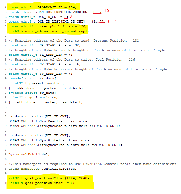
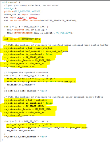
For example, from the attached screenshot, I am not sure how to change the highlighted code suite for the AX-12A. Also, can I ask what is the difference between the BROADCAST_ID and DXL_ID_CNT? Why the DXL_ID_CNT is used in the dxl.torqueOff and dxl.setOperatingMode but BROADCAST_ID is used in the dxl.torqueOn?


Best
Xiangyu

BROADCAST_ID is a special DXL ID which applies to ALL DXLs in your robot at once. So dxl.torqueOn(254) is equivalent to 3 commands dxl.torqueOn(1); dxl.torqueOn(2); dxl.torqueOn(3); (when applied to your case).

DXL_ID_CNT is the number of DXLs in your robot which is 3 in your case, and you already got that correctly. Your array DXL_ID_LIST[] is also set correctly.

For the actual addresses of Parameters Goal Position and Present Position, you need to read up on the ROBOTIS e-manual information specifically for the AX-12A:

Where you can see that Goal Position is at address 30, and its data length is only 2 bytes (not 4 bytes like for X series). For Present Position, its address is 36, data length is 2 bytes.

The possible Goal Position values for the AX-12A can only be between 0 and 1023.

The details of the actual Sync Read/Write packet set up should not have to be modified.

Hi, thank you for your advice!

So I will have a try that change the int32_t goal_position[2] = {1024, 2048}; to int32_t goal_position[2] = {0,1023}; and leave other details as the original. See if that works.

Thank you

Hello @Huiduan

The Goal Position parameter on AX-12A is only 2 bytes long, so you shouldn’t use int32_t, use int16_t instead.

Also I forgot to mention that AX12As can do Sync Write but NOT Sync Read.

Hello,

I changed all the int32_t to int16_t, but it still not works. Can I upload the entire code and could you please help me to check?

Also, if I would like to set different angle for each servo motor , how should I change the code?

The information for possible Goal Position values and corresponding horn angles is listed here

For example, “512” is straight up position for the horn.

You can also upload your code so that I can check it.
Which ARDUINO board are you using? OpenRB-150, OpenCM-904? Or something else?

I have modified the original ROBOTIS code so that it can work with two AX-12A

// Copyright 2021 ROBOTIS CO., LTD.
// Modified for AX12-A  3/8/2023
#include <Dynamixel2Arduino.h>
#define DXL_SERIAL   Serial1
#define DEBUG_SERIAL Serial
const int DXL_DIR_PIN = A5; // DYNAMIXEL Shield DIR PIN for Adafruit ESP32 V2

const uint8_t BROADCAST_ID = 254;
const float DYNAMIXEL_PROTOCOL_VERSION = 1.0;  // AX12A
const uint8_t DXL_ID_CNT = 2;
const uint8_t DXL_ID_LIST[DXL_ID_CNT] = {13, 14};
const uint16_t user_pkt_buf_cap = 128;
uint8_t user_pkt_buf[user_pkt_buf_cap];

// Starting address of the Data to read; Present Position = 36 for AX12A
const uint16_t SR_START_ADDR = 36;
// Length of the Data to read; Length of Position data of AX12A is 2 bytes
const uint16_t SR_ADDR_LEN = 2;
// Starting address of the Data to write; Goal Position = 30 for AX12A
const uint16_t SW_START_ADDR = 30;
// Length of the Data to write; Length of Position data of AX12A is 2 bytes
const uint16_t SW_ADDR_LEN = 2;

typedef struct sr_data{
  int32_t present_position;
} __attribute__((packed)) sr_data_t;
typedef struct sw_data{
  int32_t goal_position;
} __attribute__((packed)) sw_data_t;

sr_data_t sr_data[DXL_ID_CNT];
DYNAMIXEL::InfoSyncReadInst_t sr_infos;
DYNAMIXEL::XELInfoSyncRead_t info_xels_sr[DXL_ID_CNT];

sw_data_t sw_data[DXL_ID_CNT];
DYNAMIXEL::InfoSyncWriteInst_t sw_infos;
DYNAMIXEL::XELInfoSyncWrite_t info_xels_sw[DXL_ID_CNT];

Dynamixel2Arduino dxl(DXL_SERIAL, DXL_DIR_PIN);

//This namespace is required to use DYNAMIXEL Control table item name definitions
using namespace ControlTableItem;

int16_t goal_position[2] = {450, 550};  // AX12A rotates between positions 450 and 550
uint8_t goal_position_index = 0;

void setup() {
  // put your setup code here, to run once:
  DEBUG_SERIAL.begin(115200);
  while(!DEBUG_SERIAL);

  dxl.begin(1000000);  // AX12A set to 1 Mbps
  dxl.setPortProtocolVersion(DYNAMIXEL_PROTOCOL_VERSION);

// Prepare the SyncRead structure
  for(int i = 0; i < DXL_ID_CNT; i++){
    dxl.torqueOff(DXL_ID_LIST[i]);
    dxl.setOperatingMode(DXL_ID_LIST[i], OP_POSITION);
  }
  dxl.torqueOn(BROADCAST_ID);

  // Fill the members of structure to syncRead using external user packet buffer
  sr_infos.packet.p_buf = user_pkt_buf;
  sr_infos.packet.buf_capacity = user_pkt_buf_cap;
  sr_infos.packet.is_completed = false;
  sr_infos.addr = SR_START_ADDR;
  sr_infos.addr_length = SR_ADDR_LEN;
  sr_infos.p_xels = info_xels_sr;
  sr_infos.xel_count = 0;  

  for(int i = 0; i < DXL_ID_CNT; i++){
    info_xels_sr[i].id = DXL_ID_LIST[i];
    info_xels_sr[i].p_recv_buf = (uint8_t*)&sr_data[i];
    sr_infos.xel_count++;
  }
  sr_infos.is_info_changed = true;

  // Fill the members of structure to syncWrite using internal packet buffer
  sw_infos.packet.p_buf = nullptr;
  sw_infos.packet.is_completed = false;
  sw_infos.addr = SW_START_ADDR;
  sw_infos.addr_length = SW_ADDR_LEN;
  sw_infos.p_xels = info_xels_sw;
  sw_infos.xel_count = 0;

  for(int i = 0; i < DXL_ID_CNT; i++){
    info_xels_sw[i].id = DXL_ID_LIST[i];
    info_xels_sw[i].p_data = (uint8_t*)&sw_data[i].goal_position;
    sw_infos.xel_count++;
  }
  sw_infos.is_info_changed = true;
}

void loop() {
  // put your main code here, to run repeatedly:
  static uint32_t try_count = 0;
  uint8_t i, recv_cnt;
  
  // Insert a new Goal Position to the SyncWrite Packet
  for(i = 0; i < DXL_ID_CNT; i++){
    sw_data[i].goal_position = goal_position[goal_position_index];
  }

  // Update the SyncWrite packet status
  sw_infos.is_info_changed = true;

  DEBUG_SERIAL.print("\n>>>>>> Sync Instruction Test : ");
  DEBUG_SERIAL.println(try_count++);
  
  // Build a SyncWrite Packet and transmit to DYNAMIXEL  
  if(dxl.syncWrite(&sw_infos) == true){
    DEBUG_SERIAL.println("[SyncWrite] Success");
    for(i = 0; i<sw_infos.xel_count; i++){
      DEBUG_SERIAL.print("  ID: ");DEBUG_SERIAL.println(sw_infos.p_xels[i].id);
      DEBUG_SERIAL.print("\t Goal Position: ");DEBUG_SERIAL.println(sw_data[i].goal_position);
    }
    if(goal_position_index == 0)
      goal_position_index = 1;
    else
      goal_position_index = 0;
  } else {
    DEBUG_SERIAL.print("[SyncWrite] Fail, Lib error code: ");
    DEBUG_SERIAL.print(dxl.getLastLibErrCode());
  }
  DEBUG_SERIAL.println();

  delay(250);


  // Transmit predefined SyncRead instruction packet
  // and receive a status packet from each DYNAMIXEL
  recv_cnt = dxl.syncRead(&sr_infos);
  if(recv_cnt > 0) {
    DEBUG_SERIAL.print("[SyncRead] Success, Received ID Count: ");
    DEBUG_SERIAL.println(recv_cnt);
    for(i = 0; i<recv_cnt; i++){
      DEBUG_SERIAL.print("  ID: ");
      DEBUG_SERIAL.print(sr_infos.p_xels[i].id);
      DEBUG_SERIAL.print(", Error: ");
      DEBUG_SERIAL.println(sr_infos.p_xels[i].error);
      DEBUG_SERIAL.print("\t Present Position: ");
      DEBUG_SERIAL.println(sr_data[i].present_position);
    }
  }else{
    DEBUG_SERIAL.print("[SyncRead] Fail, Lib error code: ");
    DEBUG_SERIAL.println(dxl.getLastLibErrCode());
  }
  DEBUG_SERIAL.println("=======================================================");

  digitalWrite(LED_BUILTIN, !digitalRead(LED_BUILTIN));
  delay(750);
}

And I have verified that it works OK for Sync Write, but it will fail for Sync Read.

Hi roboteer,

Thank you for the help. I have tried the code you provided. I opened a blank sketch and copied the code. It did not work at the beginning. And I tried to change the library from Dynamixel2Arduino to DynamixelShield. Then the code works. But the code is to sync the servo motors to move in same angle, what if I need to request different angles for each motor, how should I change the code?

Best wishes
Huiduan

That code was for my own board so that it has a different DXL_DIR_PIN than yours, I am sure. Which controller are you using? You can try this free Kindle sample to learn more about Arduino and ROBOTIS hardware:

https://www.amazon.com/Using-ARDUINO-ROBOTIS-Systems-Ngoc-ebook/dp/B0BPXGQ6YX

Right now, the DXLs Goal Positions are defined by the array goal_position[2] = {450, 550}; . Whereas, goal_position[0] is the first and common GP of both DXLs (=450) and goal_position[1] is the second and common GP of both DXLs (=550). So you will have to “rethink” the design of this goal_position array, and to make goal_position[0] points to DXL 1 only and goal_position[1] points to DXL 2 only, etc…

See the following post, where I used a different kind of Sync Read Write packet (deprecated by ROBOTIS, but I like it better) where every time that Function loop() iterates, it chooses a random GP value for each DXL.

goal_position[i] = (uint16_t) random(0,1023); // when applied to your set up with AX12s

You should be able to modify that approach for your needs.

Thank you for your very helpful reply. Do you have any references regarding controlling 2 or more Dynamixel motors with different inputs? Does OpenRB support controlling 2 Dynamixel motors with different angle codes? Where should I connect the second servo, on servo 1 or the second port on OpenRB?

@resdul

You need to reread Sub-Section 1.1 of the free Kindle sample. All Dynamixels are connected into a Network so it does not matter where they are plugged into the RB-150. You can even daisy chain them together. However each of them needs its own unique ID which is a number between 0 and 255. But the numbers 100 and 200 are reserved. All DXLs have ID=1 when they are new. Do you know how to change that default value? What kind of hardware and software do you have/use at present? Are you using Windows?

The Arduino IDE already gave you lots of examples using SetGoalPosition(). Did you understand them OK?

I am new to using Dynamixel servos, and I have purchased various controllers to support them, including Uno, Mega 2560, Dyna Shield, and OpenRB. I have two Dynamixel servos, and I want them to operate at different angles. I am unsure how to change their IDs. Can you assist me in understanding how to do this? I have attempted to create a program as shown below, but both servos remain inactive. I am using Windows with the OpenRB 150 controller and the Arduino IDE software.

#include <Dynamixel2Arduino.h>

// Please modify it to suit your hardware.
#if defined(ARDUINO_AVR_UNO) || defined(ARDUINO_AVR_MEGA2560) // When using DynamixelShield
#include <SoftwareSerial.h>
SoftwareSerial soft_serial(7, 8); // DYNAMIXELShield UART RX/TX
#define DXL_SERIAL Serial
#define DEBUG_SERIAL soft_serial
const int DXL_DIR_PIN = 2; // DYNAMIXEL Shield DIR PIN
#elif defined(ARDUINO_SAM_DUE) // When using DynamixelShield
#define DXL_SERIAL Serial
#define DEBUG_SERIAL SerialUSB
const int DXL_DIR_PIN = 2; // DYNAMIXEL Shield DIR PIN
#elif defined(ARDUINO_SAM_ZERO) // When using DynamixelShield
#define DXL_SERIAL Serial1
#define DEBUG_SERIAL SerialUSB
const int DXL_DIR_PIN = 2; // DYNAMIXEL Shield DIR PIN
#elif defined(ARDUINO_OpenCM904) // When using official ROBOTIS board with DXL circuit.
#define DXL_SERIAL Serial3
#define DEBUG_SERIAL Serial
const int DXL_DIR_PIN = 22;
#elif defined(ARDUINO_OpenCR) // When using official ROBOTIS board with DXL circuit.
#define DXL_SERIAL Serial3
#define DEBUG_SERIAL Serial
const int DXL_DIR_PIN = 84; // OpenCR Board’s DIR PIN.
#elif defined(ARDUINO_OpenRB) // When using OpenRB-150
//OpenRB does not require the DIR control pin.
#define DXL_SERIAL Serial1
#define DEBUG_SERIAL Serial
const int DXL_DIR_PIN = -1;
#else // Other boards when using DynamixelShield
#define DXL_SERIAL Serial1
#define DEBUG_SERIAL Serial
const int DXL_DIR_PIN = 2; // DYNAMIXEL Shield DIR PIN
#endif

const uint8_t DXL_ID = 1;
const uint8_t DXL_ID2 = 3;
const float DXL_PROTOCOL_VERSION = 1.0;

Dynamixel2Arduino dxl(DXL_SERIAL, DXL_DIR_PIN);

//This namespace is required to use Control table item names
using namespace ControlTableItem;

void setup() {
// put your setup code here, to run once:

// Use UART port of DYNAMIXEL Shield to debug.
DEBUG_SERIAL.begin(115200);
while(!DEBUG_SERIAL);

// Set Port baudrate to 57600bps. This has to match with DYNAMIXEL baudrate.
dxl.begin(1000000);
// Set Port Protocol Version. This has to match with DYNAMIXEL protocol version.
dxl.setPortProtocolVersion(DXL_PROTOCOL_VERSION);
// Get DYNAMIXEL information
dxl.ping(DXL_ID);
dxl.ping(DXL_ID2);

// Turn off torque when configuring items in EEPROM area
dxl.torqueOff(DXL_ID);
dxl.setOperatingMode(DXL_ID, OP_POSITION);
dxl.torqueOn(DXL_ID);

dxl.torqueOff(DXL_ID2);
dxl.setOperatingMode(DXL_ID2, OP_POSITION);
dxl.torqueOn(DXL_ID2);

// Limit the maximum velocity in Position Control Mode. Use 0 for Max speed
dxl.writeControlTableItem(PROFILE_VELOCITY, DXL_ID, 30);
// Limit the maximum velocity in Position Control Mode. Use 0 for Max speed
dxl.writeControlTableItem(PROFILE_VELOCITY, DXL_ID2, 30);
}

void loop() {
// put your main code here, to run repeatedly:

// Please refer to e-Manual(DYNAMIXEL Shield) for available range of value.
// Set Goal Position in RAW value
dxl.setGoalPosition(DXL_ID, 1023);
dxl.setGoalPosition(DXL_ID2, 0);

int i_present_position = 0;
float f_present_position = 0.0;

int i_present_position2 = 0;
float f_present_position2 = 0.0;

while (abs(1023 - i_present_position) > 10)
{
i_present_position = dxl.getPresentPosition(DXL_ID);
DEBUG_SERIAL.print("Present_Position(raw) : ");
DEBUG_SERIAL.println(i_present_position);
}
delay(1000);

// Set Goal Position in DEGREE value
dxl.setGoalPosition(DXL_ID, 170, UNIT_DEGREE);

while (abs(170 - f_present_position) > 2.0)
{
f_present_position = dxl.getPresentPosition(DXL_ID, UNIT_DEGREE);
DEBUG_SERIAL.print("Present_Position(degree) : ");
DEBUG_SERIAL.println(f_present_position);
}
delay(1000);

//SSSSSSSSSSSSSSSSSSSSSSSSSSSSSSSSSSSSSSSSSSSSSSSSSSSSSSSSSSSSSSSSSSSSSS//
while (abs(0 - i_present_position2) > 10)
{
i_present_position2 = dxl.getPresentPosition(DXL_ID2);
DEBUG_SERIAL.print("Present_Position(raw) : ");
DEBUG_SERIAL.println(i_present_position2);
}
delay(1000);

// Set Goal Position in DEGREE value
dxl.setGoalPosition(DXL_ID2, 120, UNIT_DEGREE);

while (abs(120 - f_present_position2) > 2.0)
{
f_present_position2 = dxl.getPresentPosition(DXL_ID2, UNIT_DEGREE);
DEBUG_SERIAL.print("Present_Position(degree) : ");
DEBUG_SERIAL.println(f_present_position2);
}
}
I can see that you were trying to use the sketch position_mode.ino to start from, and that was a good step. However, because ROBOTIS produces so many types of actuators, you should ALWAYS check the specific CONTROL TABLE of your specific DXL before applying the provided example sketches.

So if you go to this web link for the AX-12

You are going to find out that the parameter PROFILE_VELOCITY does not exist for the AX-12. PROFILE_VELOCITY only applies for the newer X-series, while the AX-12 uses the MOVING_SPEED parameter, so you need to use the following statements to set up the “Speed” of your AX-12s when they are in Position Control mode.

dxl.writeControlTableItem(MOVING_SPEED, DXL_ID, 512); // range 0-1023
dxl.writeControlTableItem(MOVING_SPEED, DXL_ID2, 512); // range 0-1023

More details for MOVING_SPEED are available here

The lesson to remember is that if you want to use writeControlTableItem(), you better check with the ACTUAL Control Table for your specific actuator.

Fortunately, all the set and get types of functions are applicable to ALL Dynamixels.

BTW, in the last post, I forgot to mention that as PROFILE_VELOCITY points to Address 112 which is not used in the Control Table for AX-12. But to be safe, you’ll need to recover the Firmware on the AX-12 before using it again.

Hi, I would like to buy your book as I seem very interested. I want to learn about robots, but the book is not available in my country. any suggestion? and I created a new forum to discuss about that and my learning experiments

Have you tried to get the Kindle version from Amazon? It should be available directly from the web assuming you have an Amazon account. Also ROBOTIS have dealers all over the world. Can you contact the dealer where you get your hardware from? They may be able to work with ROBOTIS USA to get you a hard copy. Please contact @Jonathon directly to let him know which part of the world is your country in.

Robotis USA sells the Arduino book too: