I’d like to share the progress of my current project with OpenCR.
I started with writing my own bootloader and firmware based on original OpenCR from Eclipse IDE, but thought it might be more useful if this can be used on Arduino IDE.
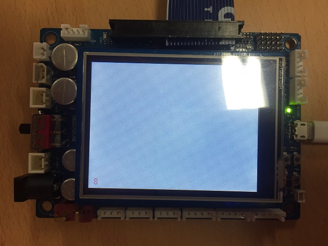
Lighting up the 2.8" Arduino TFT-LCD was a piece of cake with given example from Arduino.
However, this was my first experience working with any kind of camera so I was a little excited and nervous at the same time.
The OpenCR had very limited available GPIO pin for OV7725 and I wasn’t able to use MCO pins for CMOS clock.
So I decided to accept my coworker’s advice; use PWM from GPIO.
Bitbanging GPIO pin requires interrupt to generate exact frequency so I thought PWM would be a good approach.
Then, I googled for OV7725 examples and referred some of them to figure out how it works along with the datasheet from sparkfun.
Also AL422B datasheet was useful to figure out the read/write timing of FIFO memory.
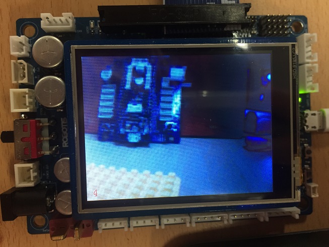
It took a while to get this point.
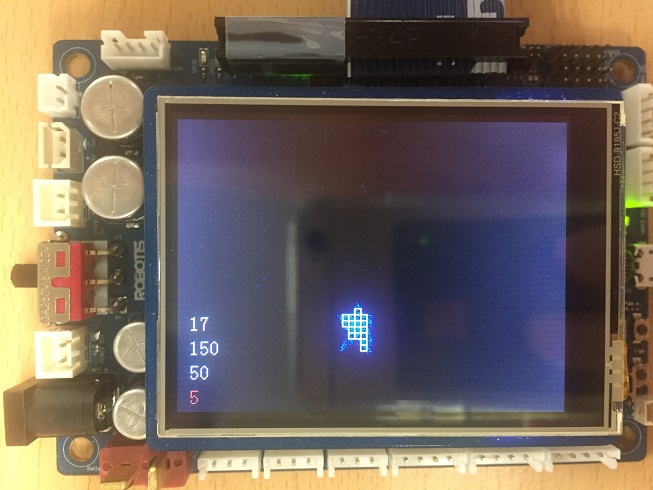
The number on left bottom corner is the FPS but the actual value should be doubled, so I was getting around 7~8 FPS with 320x240 image.
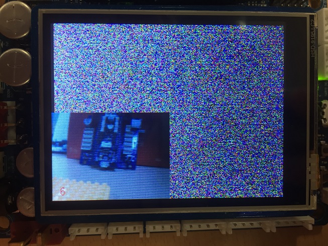
Squeezed the size of image for smoother and faster image processing.
At this point, I was getting around 11~12 FPS without using SPI DMA, but when I use the DMA, the FPS bumped up to 15 FPS.
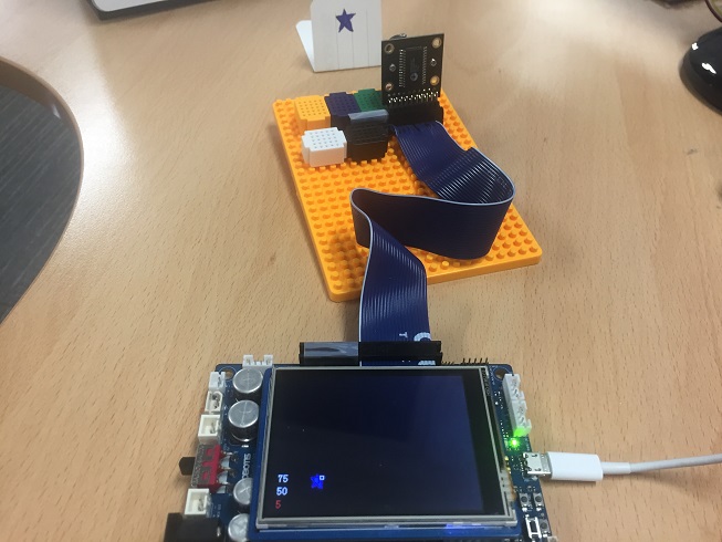
I set blue for detecting color and drew a blue star on a paper.
I used 5x5 pixel block and set the density to about 50% to figure out whether the desired color is dominating the block or not, therefore, if more than 13 pixels are blue, it’ll be detected as an object.
In this picture, I only set a single cell and shows the last object detected with its xy coordinate.
Increased more cells to detect(up to 30), and looks like below.
Later on, I restored original camera image and drew detected cells over it with highlighted cell(in red) that finds the center of the biggest object.
The image processing and object detection algorithm is written without referring other famous library like openCV(as this is my first time handling with camera and image), so it may have some pitfall that I didn’t expect, but I liked it because it only consumes a couple fps.
The FPS in this video is corrected and it shows around 10~11 fps after the processing.
I’ll keep working on it and probably will be able to track detected object with pan-tilt Dynamixel structure soon.
Please feel free to enlighten me to improve this example with your idea.
Once it is completed, I’ll add it with the next OpenCR firmware release.
Thank you.
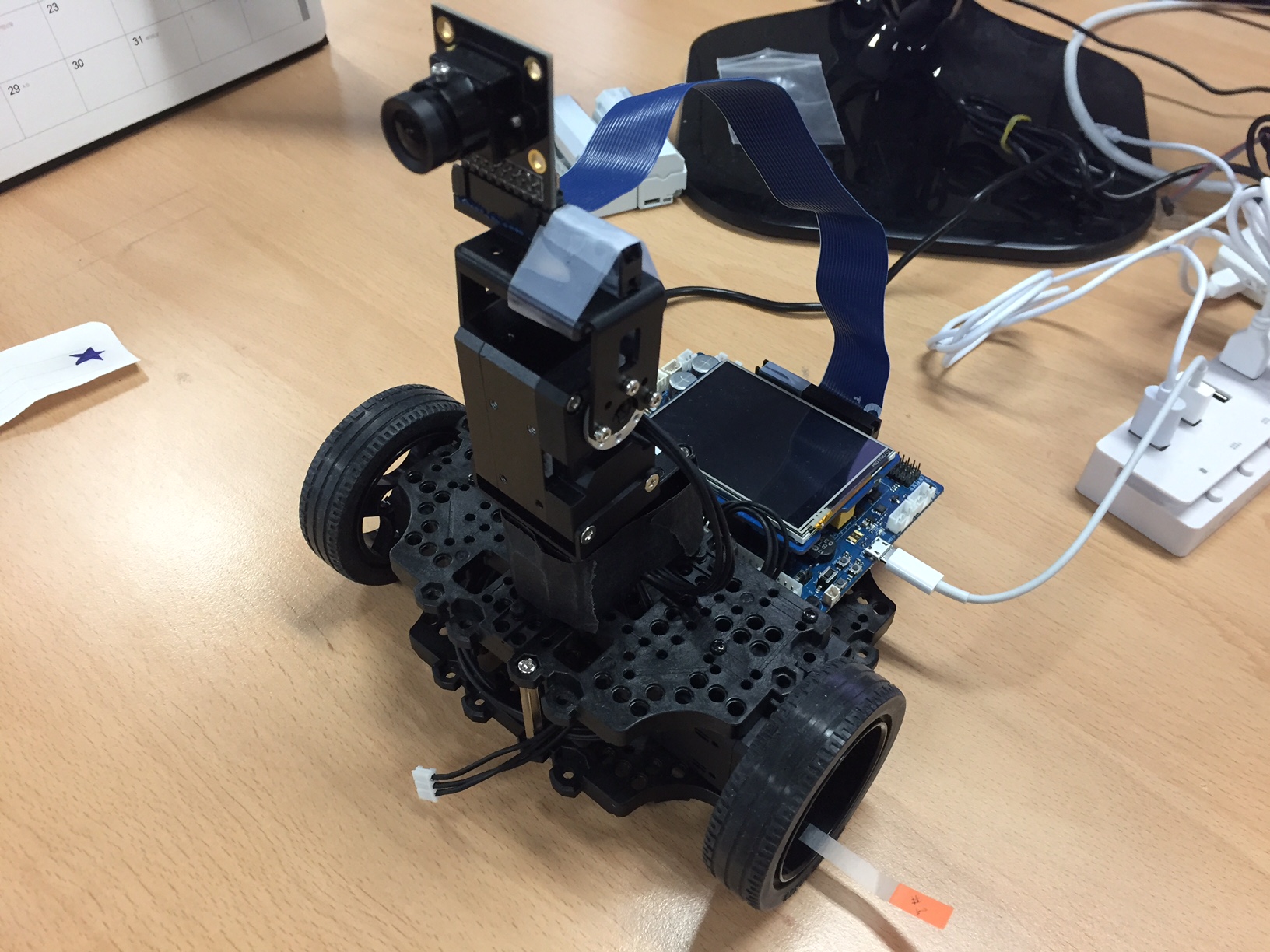
Tracking the object with 2 axis(Pan & Tilt) Dynamixel is available now.
For some reason, I sometimes get corrupted image after I attached the OV7725 camera module on the Tilt module metal frame.
Not sure whether this is because of the noise vulnerable flat cable or other reasons.
The final FPS is about 12~13fps.
I can increase Dynamixel speed in order to make it faster to follow the object, but the motion is not as smooth as it is shown in the video.
Based on the application, the speed can be optimized.
======= Edited : Test Result of raw FPS without displaying LCD =========
Upon request from @Leon_Ryuwoon_Jung, I commented out image processing, Dynamixel tracking and LCD drawing codes.
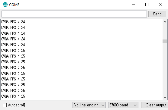
So the following FPS shows the maximum rate of assembling frame acquired from FIFO memory of OV7725+AL422B module.
QVGA(320*240) : 25 FPS
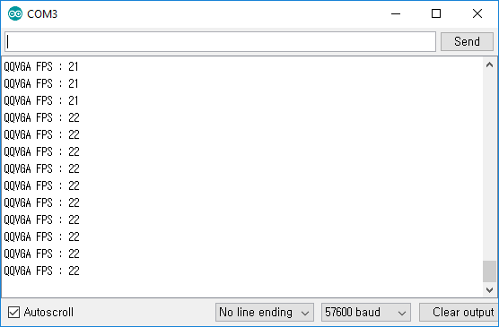
QQVGA(160*120) : 22FPS
The reason QQVGA drops 2~3 frame is because it shrinks QVGA down to QQVGA.
Thanks!
Wondering, will you also be integrating some of this into the Turtle ROS code?
I might have to try some of this out. I might be tempted to do it with the ILI9341 displays as I have several of them and have played with them in the past… Might have to pick up a camera!
Thank you for the idea of integrating into ROS.
The initial purpose of this was to see how far OpenCR can manage without having another processor.
Creating two QVGA sized image buffer was already causing RAM overflow issue, but I hope QQVGA will be a useful example for certain people.
I didn’t have chance to test on various devices, so please let me know if there’s a good way to improve the example for other compatible devices.
Thank you!
As mentioned I will probably use an ILI9341 display probably with touch. Could use one of the ones from Adafruit (either the shield or breakout board version) or I might use one of the ones, that I have that I ordered from PJRC (Teensy) https://www.pjrc.com/store/display_ili9341_touch.html
Still trying to figure out things about the capabilities of this board.
Note: the links to the datasheet and reference manual in the document:
Are broken… At least when I last checked.
So for example I am unsure how much memory do these boards have? I believe program size up to 768K, but I am not sure about how much RAM?
As we already discussed I have a version of the Adafruit ILI9341 library working on this board, but may choose to make a version of my faster version, that works on Teensy boards:
This version has the option of using a backing frame buffer on some Teensy boards T3.5 and 3.6. It also has the ability to use DMA to update the display Asynch, both as a single shot and continuous.
What I wonder about this board is I know that there are at least two SPI busses. One is used by the IMU, and I have not found any place where you can use this buss for other purposes. That is it would be great if you could have the display and camera on two different SPI busses and potentially use DMA to communicate with both. So in theory you could have the display being updated at the same time as the camera is reading in the next image.
Again I was thinking of mounting a display on the top of the Waffle. Not sure yet if to use Arduino display which implies moving the CR1 or using a breakout board. In either case would want to be able to use some of the other IO pins and in some cases same pins (I2C, SPI…). So will figure out ways to do this.
a) Use breakout board…
b) Maybe have Arduino duplicate shield that goes between the board and display…
Arducam mini seems fine as long as I set GPIO 8~12 to SPI4 and modify SPI driver.
I2C2 on GPIO 1&2 will be available in the next update(tomorrow) as my OpenCR-Camera example is using them.
I’ll try to find a domestic shop where I can purchase the camera module.
One of my colleague also mentioned about switching image buffers for displaying to LCD and receiving from camera.
But OpenCR has RAM size of 256KB and single 16bit QVGA buffer takes about 153KB so it doesn’t have enough RAM.
Although I can try increasing RAM size by adjusting memory areas, I wanted to keep the basic structure the same as much as possible.
For the QVGA image processing, I assigned a bit-wise masked image buffer(9.6KB) to RAM_DTCM that has 65KB free area in total, but 7~8 fps with QVGA is kinda slow I think.
My next goal will be tracking and following the detected object
Trying to figure out how to reuse TurtleBot3 motor driver source code though.
Likewise only room for one Frame buffer in memory. So the question might be, can you get all of the timings in a manor where for example maybe as the camera has read half a frame into memory, you have time to do any processing, and the code starts up to start the screen update… So one is always chasing the other. The question would be could everything synchronized the way you want…
Thanks for the hints about memory, and also good to hear that there may be support for additional SPI and I2C buses.
I’ve merged your recent update for SPI into my OpenCR repository for the test.
Thanks to your enhanced SPI, I was able to acquire higher FPS(about +4 FPS)!
Awesome!!
Below is the QQVGA screen that was originally 12~13 fps, and with your code, now I’m getting 16~17 fps
The best thing is that now I’m getting almost doubled fps in full screen mode(8~9 fps) that looks pretty smooth and possibly pull more resource from the mcu
I’ll update the Arduino IDE example in the next update.
Thank you so much for your contribution!


")
")