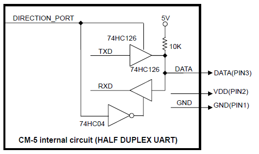
This photo describes what is at that site for the AX-12A servos I am trying to get to work.
I do not understand some of what is described on this schematic.
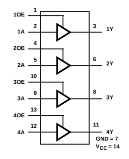
Are there two HC126 chips or do I use one, single HC126?
What does DIRECTION_PORT on this schematic mean?
I have some of my Half Duplex UART circuitry already made and I am trying to complete the circuit now.
Seth
P.S. If you understand what I am trying to understand, please do make time for this post. For instance, where does 1OE from the HC126 go? Is it used or is that pin supposed to float or be grounded like the rest that are not used?
Sorry, hopefully someone from Robotis or the like can give you better answers.
I have not used that setup so I would have to figure it out… I have done it several different ways, depending on which Microcontroller I was using and how safe/reliable I wanted it to be. But again I only do this for my own stuff…
Example ways: with some simple AVR +5v boards and sometimes even with Teensy boards which output 3.3v I do it with no hardware, other than maybe a current limiting resistor. With the AVR sometimes you can simply tie the RX pin to the TX pin and connect both to the DXL pin… This requires software to know when to change using the UART…
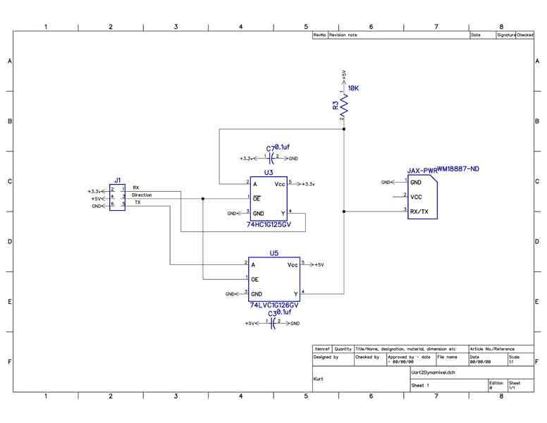
The closest to what you have is using one 125 chip and one 126… Something like:
Now which 125/126 to use I have heard different things…
I have also done it with one chip… TC7WT141FU by Texas Instruments. Which needs some external resistors, both for Pull ups and resistor divider… Don’t see a picture right now. There is/was one by a user jwatte up on the Trossen forum that posted the circuit, but their forum appears to be dead right now.
Hey…thank you for this idea. I will test it soon. If you are definite this schematic is the one to use, I will try to get it working soon. Right now, I only have the HC04 and HC126. In your schematic, you show JAX-PWR.
What is JAX-PWR? Is that the microcontroller you used? I am using a logic of 3.3v w/ my Linux computer for now. So…I am at a loss for now.
Seth
P.S. Are you using the HC125 b/c it has an OE pin on it or for another reason? I noticed my HC04 does not have an OE pin on it. Just some I/O, Vcc, and GND. Anyway, thank you.
Some of the parts I have used (again not saying they are the best or not… But from my earlier XLS file)
WM18887-ND WM18887-ND 8 BIOLOID 3 JAX1, JAX2, JAX3, JAX4, JAX5, JAX-PWR
SUP75P03-07-E3-ND MOSFET P-CH 30V 75A TO220AB 1 TO220AB 3 Q2
SUP75P03-07-E3-ND MOSFET P-CH 30V 75A TO220AB 1 TO220AB 3 Q2
1727-6036-1-ND IC BUS BUFF DVR TRI-ST 5TSOP 1 SOT23-5 U3
1727-6066-1-ND IC BUFF DVR TRI-ST N-INV 5TSOP 1 SOT23-5 U5
Again as I am not an EE, take this with grain of salt… Some of this design was borrowed from an earlier board (Arbotix Pro) that Trossen Robotics sold, which I show with the extra stuff that allows the MicroController (in this case a Teensy 3.6) to turn the power on and off to the servos. I did leave one of the servo connectors with power always connected (not going through transistors), to allow for other things to be powered off of this. Example I might go off of this connector and make a power connection back to something like an RPI…
Seth here. I will try both of the schematics and I reply or return service once things are situated and tested.
…
I cannot thank you enough. Even though I have only been working on this project for a short period, I have found a couple of circuit lessons thus far.
Seth
P.S. To tell you the truth, I am not an elect. engineer either nor am I a mechanical engineer. I mostly tinker w/ things and learn as I go. I have a selected background in developing hardware, i.e. esp. servo hardware from a 3.3v beaglbone black to a 12v (11.2v recommended) servo.
I’m sorry for the late reply. @silver2row if you have HC126, it should have 4 inputs and outputs as below.
You can use your HC04 to provide inverted signal for the RX gate.
Please note that if you are using 3.3V power source for both IC, 5V pull up across the 10Kohm resistor is required as DYNAMIXEL TTL data is 5V level digital signal.
Some AVR mcu may not require this 5V and 10K pull up resistor as the MCU can handle 5V digital input/output signals.
Is the Direction_Port on the schematic a Dynamixel port on the Servo or does that pin come from another source, i.e. is that my dev. board I use?
Also…where the schematic states TX_Data and RX_Data, where do those pins go to? Obviously, I am new at this type of circuit w/ these types of buffer gate chips.
If you find time at any point, please let me know.
Seth
P.S. Until then, I will be trying out the schematic again and again. Do you think I need a dc-dc converter or a logic-level shifter for this type of circuit?
But the TX_data, RX_data, and Direction_Port are three IO pins that are needed from your dev board or the like.
In particular the Dynamixel Servos use a Half duplex protocol, that is TTL data pin goes to you dynamixel servos and it carries the Serial data to and from all of the servos.
You need to have the direction port set to know which direction the data should be going. That is are you sending data from your host to the servos or receiving data form the servos.
Your controlling software needs to be knowledgeable enough to know when to set and clear this IO signal. Most of the time the code will do something like:
digitalWrite(Direction_Port, HIGH); // assumes HIGH is for TX, may be low
<Do Serial.writes to output your packet>
DynamixelSerial.flush(); // make sure the TX fully completes
digitalWrite(Direction_Port, LOW); // go to RX mode.
And you need to make sure to not do this when you are expecting a servo to respond, or your packet will collide with the data the servo is trying to send.
@silver2row Sorry for the late reply. I just came back to work from unusual serial holidays + weekend.
Like @Kurt mentioned above, TX_Data, RX_Data, Direction_Port supposed to be connected to the Uart TX pin, Uart RX pin, one of GPIO pins in your MCU or the “BBB” respectively.
Since you are using 3.3V logic board, you need to pull up the DYNAMIXEL TTL Data pin to 5V across the 10kohm resistor.
You could try skipping this 5V and pull up resistor, but the communication could be very unstable.
From the suggested schematic that I posted in the above, it looks like the 5V pull up on TTL data pin is not working well.
Though 3.3V will be still considered as HIGH for 5V TTL, this will be very vulnerable to a signal noise.
Instead of using 5V pull up across the 10Kohm resistor, it will be better to use buffers on the TTL bus as Kurt suggested.
Thank you.
You guys…thank you again for adding more support to this cause. I tried to make some circuitry. I failed so far but I think I figured out how to make an amplifier out of the HC04 and HC126. I tested the circuit instead of directly plugging it in to the BBB or Servo. Phew. I need to configure things more before I can understand what it is that needs to happen.
On the HC126, I think I misread what exactly I need to do to conform to its standard and the instructions for that specific chip. Dodged another bullet. Phew. So, my chips are still intact and the Servo/MCU is not damaged either.
Seth
P.S. I will keep plugging at it to see if I can alter things within the chip with source and/or how to communicate with both chips in @ROBOTIS-Will diagram. Anyway, I am playing it safe for now. I only have so many boards to damage before opting to purchase new ones. So, safety freak I “be.”
Sir, is the Direction_Port a GPIO or PWM pin? I can use either but I am unaware of what Direction_Port means.
Seth
P.S. I have the communication down pat but the Direction_Port is the missing link so far on my end. The AX-12A turns on for a bit but then the LED fades out. I tried 9v and 12v. I am getting close. Anyway, I will produce a schematic when it is all done and completed.
The DIRECTION_PORT should be connected to a GPIO pin so that it can control the Input / Output direction of data from the buffers. [TxRxResult] There is no status packet! error means that your program failed to receive the status packet from DYNAMIXEL.
Please refer eManual for more information about the status packet.
You should set up a correct direction control in order to communicate with DYNAMIXEL.
If you are using an SBC with available USB port, you could simply use U2D2 + U2D2 PHB to control DYNAMIXEL.