@silver2row
Glad that you figured out the connection and successful communication.
DYNAMIXEL Wizard 2.0 supports 3 major OS so please refer to the eManual below.
If you are using 32bit Windows, the software should work on your machine.
@silver2row
Glad that you figured out the connection and successful communication.
DYNAMIXEL Wizard 2.0 supports 3 major OS so please refer to the eManual below.
If you are using 32bit Windows, the software should work on your machine.
@ROBOTIS-Will,
Sir…w/ the SDK, can I run ping.py as python3 ping.py and receive feedback via the console or should I type up my own source from your SDK?
Seth
P.S. I installed dynamixel_helper via pip and I am trying it now. I have failed so far but I think I need to alter the source of the DynamixelSDK to suit my needs.
Hi,
The codes in the tests directory is written to be run under Linux.
I’d recommend to check if a correct data is transmitted from the port on the control board before getting the response from DYNAMIXEL.
ping.py will work as is if you are running Protocol 2.0 DYNAMIXEL with the factory default setting on Linux.
Below products will work with ping.py example on Linux :
Hello Sir,
@ROBOTIS-Will the UART channel and GPIO onboard my SBC works. I have tested it. I need to use Protocol 1 b/c I have an AX-12A only. I have two of them.
…
Should ping.py work under Linux with Protocol 1?
Seth
Seth,
My bad, let me rephrase my last comment.
The test codes under the Protocol2_0 directory is written for Protocol 2, and you can use test codes under Protocol1_0 for your AX-12A.
If you haven’t change any setting on AX-12A, the code should work on your Linux without any change.
If you are using an embedded controller, this python code may not work as the port defined by DEVICENAME will work differently.
For more accurate information, please describe your development environment with more details such as SBC product name, OS, version, which port name your UART is assigned at, and etc.
Thank you.
Hello Sir,
Okay. No issue. I understand that I was not giving the entire view. So…
I am using a BBB (BeagleBone Black), Linux Debian 10, kernel 4.19.x, and DEVICENAME is equal to “/dev/ttyS2”.
"/dev/ttyS2" is my UART Ports onboard the BBB.
I have been running through the DynamixelSDK to change some things under silver2row on Github.com. This way, when I clone it, I can then use sudo python3 setup.py install to get things working properly.
I know I do not know a bunch about you all’s SDK so far.
Seth
P.S. My GPIO pin is P9.12 and I have it setup as GPIO. I can add a library in the source to make it so I can control the GPIO with code.
Thank you for additional information.
It looks like you haven’t modified the writePort function in the port_handler.py which will control your GPIO pin for direction control.
If you take a look at the writePort function in port_handler_arduino.cpp, you’ll see setTxEnable() and setTxDisable(). These functions control the GPIO pin of the Arduino related boards in their HAL layer. You should do the same for your python code in order to make your code work correctly when sending or receiving data.
Thank you.
@ROBOTIS-Will,
Hello. Okay, you rule. I will test this later. I was not even aware of this .cpp file called port_handler_arduino.cpp and I must have gotten mixed up in the Python source thinking that I could do everything w/ Python. Oops.
Again, and I repeat, you rule!
Seth
My pleasure!
Please let me know how it works as your case can be an important reference for other users as well.
I’m considering creating a tutorial for a similar case like this.
Hello,
Yes sir…I will test it soon so I can reply with my findings.
Seth
Hello @ROBOTIS-Will,
Why would my RX timeout and create the issue of, [TxRxResult] There is no status packet!, no status packet when my wiring seems to be correct?
I know there are a lot of differences in my circuit and the U2D2 circuit. I will purchase the U2D2 soon but I would still like to be able to compile the entire library on my Linux_SBC.
I mean…
Could my RX timeout be happening b/c of no compiled examples or could my RX timeout be b/c of my 3.3v logic from my UART connection? I can use a dc-dc converter or logic level shifter w/ ease. This is not a concern. When you have time, please try to make me understand. I can use all the help one man can get. Peace!
Okay. I was reading some more and found that compilation gives me errors under the ld prefix like so:
/usr/bin/ld: cannot find -ldxl_sbc_c
I compiled this file correctly (dxl_sbc_c). Should I have compiled it later or before the compilation of the other C/C++ examples?
Anyway, ping.c and the other examples do not compile in C or C++ even when the .so file is created. I cannot use make to compile those files. Are there any hints or ideas spanning around for this endeavor?
@silver2row - sorry I know I am not much help with this one.
A long time ago (about 7 years ago) I did play around some with the BeagleBone Black. Needles to say probably things have changed a lot since then, but back then you had to jump through hoops to enable GPIO. I don’t remember the details any more. At some point I believe you had to do something with device trees.
Again I don’t remember if any regular GPIO pins are already setup…
But that would be one of the first things I would check. And of course if it were me, I would have one of my logic analyzers setup to watch the TX, RX and Direction pin, to see if your setup is properly setting the direction to TX mode at the proper time and then switching to RX mode and to see if anything comes in on the RX pin.
And Note I would also have a 4th pin hooked up on my LA to the actual Dynamixel BUS to make sure things like what I TX actually makes it out.
Again I know that is not much help.
Hello @Kurt,
Seth here. No issue at all. I am most likely going to purchase the U2D2 and power supply to test things out (most likely).
If that does not get my motors up and running, I think I need to look deeper into the source and rearrange some items dedicated to my particular setup.
The GPIO enablement on the boards these days, for the BBB, is as easy as config-pin p9.12 gpio.
There is a “new” config-pin utility to set up modes of peripherals onboard the chip. For instance, there are many modes on one, single pin. So, say Pin 12 on P9 or p9_12 (same thing), I use a pin for UART, I can then change the pin to GPIO w/ the config-pin utility in userspace.
Seth
Hi Seth (@silver2row )
Sounds like they probably improved the BeagleBone since I played with it. I played with it for awhile and then moved on to Odroid, Edison, UP, … Then back now playing a little with RPI4. But mostly not doing anything right now with their servos.
I also don’t have one of their U2D2 which may be a perfect solution for you.
I have typically preferred to solve it using an external processor chip like the U2D2, but have done it several different ways, not sure if any of the other ways would meet your needs or not.
a) Most of the time when wanted quick and dirty and compact I would use the USB2AX by Xevel Labs - Not sure if available any more.
b) make my own USB2AX - It is an Atmega32u2… So you can use an Atmega32U4 board, which includes Leonardo, Teensy 2 and I believe others that you can get from Amazon, Mouser, digikey
b1) any other AVR based Arduino that has both USB and a Serial port that you can use at the same time.
With these you can make them safer, but or you can simply connect the RX and TX pins of the uart together and to the DXL pin of a AX like plug, and likewise common ground.
Simple to write sketch that when it receives data from the host, it enables TX and disable RX on the serial port and sends the data and when all data is sent, it disables the TX and re-enables the RX and when it receives any data on the RX it simply sends them off back to the USB…
There are usually a few other things to put in like if nothing received again on RX for a certain amount of time to do a flush on the USB port to get the data through. Or can enhance code more to know about packets and when it sees an end of packet send it then…
c) Like above but instead I use a Teensy 3.x or 4.x can do all like b)
But note: T3x outputs 3.3 v not 5v. Never had problems with servos seeing 3.3v signals. Also only some of the T3.x are 5v tolerant (T3.2, 3.5) so if you use one of these I often do direct.
Can either work like the AVR or can configure for half duplex mode and simply connect the TX pin of the UART to DXL… Note with my newer boards I put in other hardware to convert to 5v signals…
More on code and stuff if interested.
d) Just use an OpenCM9.04 board - They are made for this and cheap. Could either buy one without connectors and buy their connector
Or you can buy their one with connectors on it, which they are out of stock at least at the US store. And if you buy it with connectors than you need to adapt from XL320 connectors to AX. Can do this their more expensive and bulky way, of use their openCM 485 expansion board which also has AX servos on it.
Or at one point I made my own HUB that had one XL320 servo connector on it and I think 6 of the AX servo connectors on it plus connector to hook up power. A slightly modified version of the Trossen Robotics DXL hub.
Or what started off doing, take an XL320 cable and an AX cable, but them both in half and splice one XL connector part to an AX connector part.
Again software for this is really simple. I believe you can simply use their default firmware that comes with the OpenCM board…
It used to be with the Robotis tools, they allowed the OpenCM 9 boards to do things like upgrade servo firmware, but some more recent versions of PC software it was not enabled anymore (at least the last time I looked).
Again the U2D2 is a very good choice, but thought I would mention some of the other options.
Hello @Kurt,
Hey. I think my issue is source and not hardware. I tested all the outputs and inputs. I made sure my board could not be damaged due to the reversal of a 5v logic running into my UART/GPIO onboard the BBB.
…
Anyway, I broke down and bought the U2D2 and power adapter just in case it is me and not the config. available to me. I also am looking to find a way to alter the source for a linux_sbc, my BBB, so I can achieve communication to the actuator.
But like I say, it is always me and I need source to test. I usually use libraries instead of SDK type libraries.
I have not seen any ideas on programming these actuators just yet. They could just be too advanced for me to to use as of now or I might need a starter script. Either/or…really.
Seth
P.S. Thank you for telling me about options on my end. Since the U2D2 will be here soon or later w/ the power adapter, I will try that avenue for communicating to and from my BBB to the actuator. If you know of any starter scripts that have been made to the public, please do not hesitate to let me know. I will keep searching.
Hi Seth,
Since we cannot test with your hardware and the source code, I think it would be the best if you can share an oscilloscope image or logic analyzer result as Kurt recommended. Once we confirm the DATA and DIRECTION_PORT are working as intended, we will be able to tackle why RX is not returning from your AX-12A.
Please understand that without having any actual data, it is very difficult to guess what went wrong in customized solutions.
Thank you.
Hello Sir,
@ROBOTIS-Will, okay. I will get on it soon. Thank you for understanding.
Seth
Hello Sir,
@ROBOTIS-Will, okay. I think you gave me some perspective on what needs to happen versus what was happening on my end.
Seth
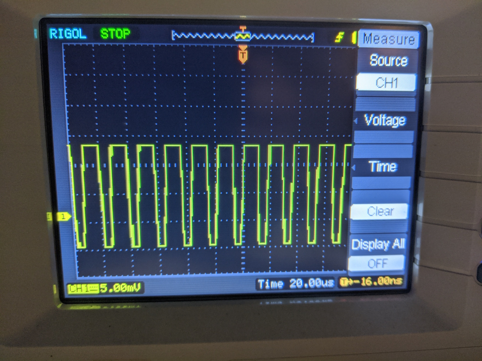
P.S. Here is the output of the GPIO on HIGH when the software runs.

@silver2row and @ROBOTIS-Will,
Seth, I am not really sure what your scope is showing. other than some signal is changing…
What would be good is to to see the state of your direction signal as well as the DXL signal, and maybe if one can show more than 2 the RX, TX pins going to your uart.
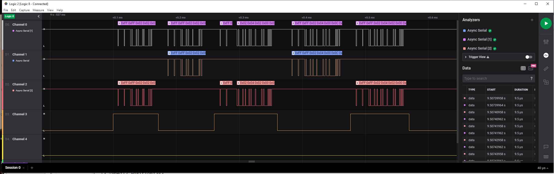
I don’t have a scope, but do most everything with logic analyzers. Here is an example of part of a run of my Find Servos program on an OpenCM9.04 (with OpenCM 485 expansion). I hooked up probes to the DXL pin on the TTL of the OpenCM9.05 (AX servo) plus on OPenCM 9.04 Serial 3 pins (24, 25) and Pin 22 which is the direction pin for OpenCM 485 expansion board… Again specific pins here specific to this setup but what it shows is pretty generic.
Part of the debug outptut showed:
 Done
Begin Searching on Port: 3
1.00
  Begin Protocol 1:
  2 Type:12 Position:568
  3 Type:12 Position:664
  4 Type:12 Position:330
  5 Type:12 Position:355
  6 Type:12 Position:373
  13 Type:12 Position:383
  14 Type:12 Position:403
  15 Type:12 Position:603
  16 Type:12 Position:248
  17 Type:12 Position:699
  18 Type:12 Position:507
  19 Type:12 Position:497
  Done
Begin Searching on Port: 3
But more interesting is the Logic Analyzer output
The top line is the DXL signals going to and from the servos. The next line is the RX pin which receives the data back from the servos. Next is the TX pin, followed by the topic of this, the Direction signal. Which you can see here is high
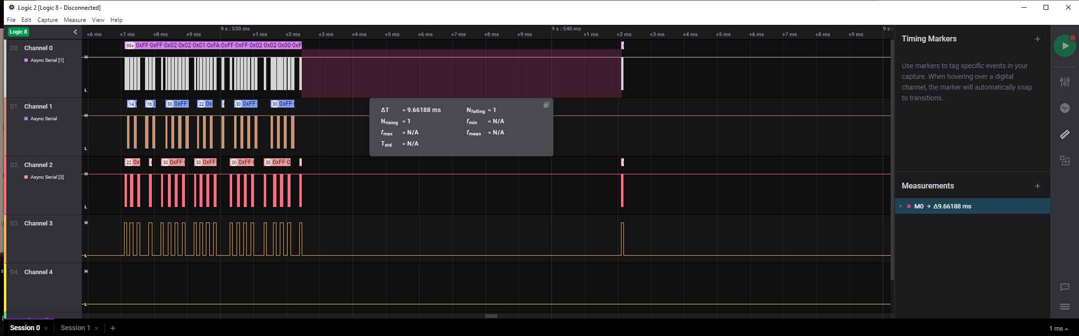
And I thought I would show also case where the actual servo is not found, you will see a gap waiting for the timeout, which in this case may be about 10ms:
I hope maybe this might help…
Side note: I have not looked very hard at seeing if the BeagleBones black Serial port(s) have built in half duplex support or not. Again did not see it in my 30 second look, but…
Hello @Kurt,
Sorry. I think some setting is misconfigured on the scope. It is an entry level scope and only has so many tools to do the job. That is the GPIO HIGH but it seems that I must have burnt the GPIO pin in use from what #beagle on Freenode people have said to me today. If that makes sense, good. If not, I am a bit flustered.
Now, I will try a new GPIO output pin. I will test the UART channels/pins later in the week. Thank you for your ideas, knowledge, and expertise in this situation.
Seth
P.S. I was able to “accurately” move the signal feed on the scope to handle a new waveform but I was told my waveform must be that way b/c of a burnt pin, e.g. my GPIO when HIGH.