안녕하세요.
U2D2연결시 불은 들어오는데 모터 동작이 되지 않습니다.
보드 문제인 것 같은데.
sudo udevadm moniotr를 실행하여 연결했을때 터미널에서 log가 찍히지 않는것을 확인했습니다.
어느 부분이 문제인지, 수리가 가능한지 문의 남깁니다.
안녕하세요.
U2D2 USB 포트가 잡히지 않고 있나요?
USB 포트가 안 뜬다면, 다른 PC에서도 확인해 주세요.
다른 PC에서도 USB포트가 뜨지 않는 상황이라면, 해당 제품은 AS 신청 및 AS 규정을 참고하여 점검을 받아봐야 합니다.
USB 포트가 뜨는 상황이라면, 전원 인가 방법 및 사용하시는 다이나믹셀의 정보 등 환경을 알려주세요.
안녕하세요.
일단, 예비용 U2D2 보드를 사용하다가 현재는
[INFO] [1733980765.412473235] [TxRxResult] Failed transmit instruction packet!
다음과 같이 패킷 전송에 실패했다고 나오더군요.
이번에도 다른 U2D2보드를 사용하니 문제없이 잘 되는데 혹시 Power hub 보드에 연결해서 사용하는게 안전할까요?
현재는 12v 전압을 따로 인가하고 있습니다.
U2D2에도 12V를 인가하고 있나요?
Power hub보드를 사용하지 않고, 별도 전원을 사용하신다면,
GND 및 데이터 라인만 연결하여 사용해주세요.

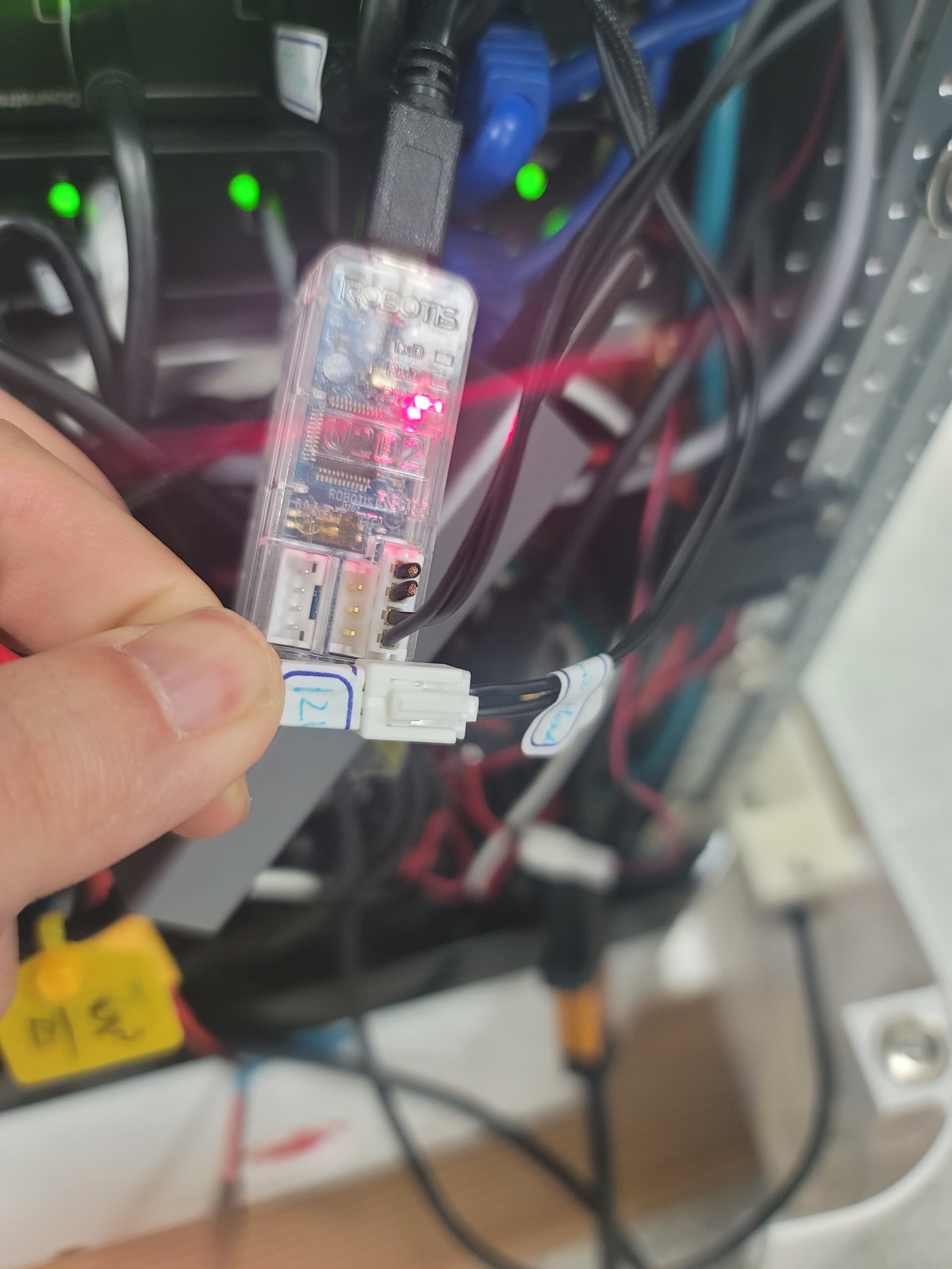
이렇게 연결하는게 맞을까요??
아래쪽 연결은 모터로 가는 12v 입니다.
전원GND 라인을 U2D2에도 연결해서 사용해야 합니다.
그런데 모터가 처음 초기 위치로는 이동하는데 그 이후 이동하지 못하는 이유는 무엇일까요??
Hello there,
Sorry but from your picture, it looks like that you put 12 V into D+ and D- ? So you may have damaged your U2D2 already and/or your Actuator also.
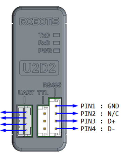
See ROBOTIS pins diagram below:


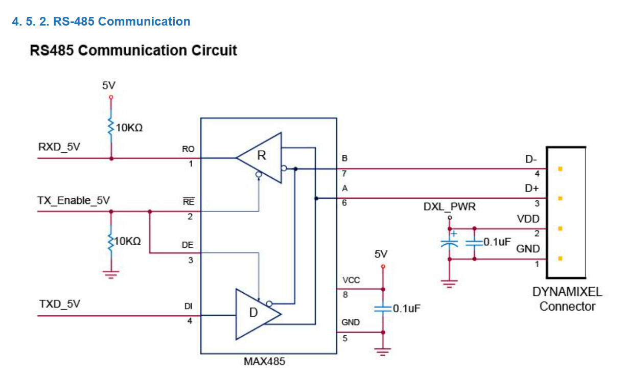
The RS-485 circuit is supporting only 5V at D+ and D- for ROBOTIS actuators. But the actual RS-485 standard allows up to 12 V for D+/D-.
You should have used an intact 4-pin cable. As you can see VDD (12V) is not connected to the U2D2 anyway.
Thank you for your detailed answer.
But I put 12V into PIN1 and PIN2.
If you look closely at the picture, 12V is inserted by disconnecting the lines of PIN1 and PIN2.
Yes. I can see that Pin1 and Pin2 are cutoff. But Pin1 is the ground (common for everything actuators, U2D2 and Controller) and Pin2 is VDD (normally 12 V for your case) which is NC to the U2D2 anyway. So you do not have to worry about the U2D2 itself getting hit by 12 V.
Pin 3 is for D+ for RS-485 and Pin 4 is for D- for RS-485. PLEASE look AGAIN at the picture of U2D2 from ROBOTIS e-manual and then look at your own picture. According to your own picture, you put 12V into Pin3 and Pin4.
YKW_R was trying to tell you this before: you need to connect the Ground, D+ and D- correctly between the U2D2 and the actuators so that you can control the actuators properly.
If you don’t believe me or @YKR_W, why do you think that you still cannot control your actuator properly so far?
I understood that pin2 is a common ground, so there is a problem when cutting and connecting like in the picture. Is it correct that I understood?
So I’m trying to bring the original line and connect it all at once and use the PHB board I got provided for power.
Thank you for your kind explanation :).
If I get it wrong, please explain it again.
As I mentioned in my first post you can use an intact 4-wire DXL cable to connect between U2D2 and the first 485 actuator. You do not have to worry about the VDD line at 12V because Pin 2 is NC (meaning Not Connected) so the U2D2 is safe from that 12V from the power for the actuator. This way you have GND, D+ and D- properly connected. The U2D2 is powered via the USB cable on its own.