Ever since I got my Portenta H7, I had been working on getting the M4 Core to work with the Dynamixel2Arduino library and my various I2C and SPI sensors, and here is what I found:
- The Dynamixel2Arduino library does work on the M4 Core, but its performance is not reliable. I am including a modified “scan_dynamixel” sketch so that others can try out on their own. You will need to put a jumper cable between Pin D5 and pin D6 via the usual MKR DXL Shield headers.
/* Scan Dynamixel example modified to run on M4 core of Arduino Portenta H7 Lite
*  Portenta Serial UART Application for sending Data from M4 to M7
*
* ================================================================================
* IMPORTANT: Connect Serial_M4 pin D5 TX to Serial_M7 pin D6 RX
* ================================================================================
*
*/

//////////////////// Start All Core M7 Programming /////////////////////
#ifdef CORE_CM7
UART Serial_M7(NC, PA_8, NC, NC);  // Pin D6 RX for M7 (Receive only)

void setup() {
   bootM4(); // get the M4 core running
   Serial.begin(115200); // regular Serial Monitor
   Serial_M7.begin(115200);
}

void loop() {
  if (Serial_M7.available()) {          // If anything comes into Serial_M7
     Serial.write(Serial_M7.read());    // Read it and send it out over Serial Monitor
  }
}

#endif
//////////////////// End All Core M7 Programming /////////////////////

//////////////////// Start All Core M4 Programming /////////////////////
#ifdef CORE_CM4
UART Serial_M4(PC_6, NC, NC, NC);    // pin D5 TX for M4 (Send only)

#include <Dynamixel2Arduino.h>

#define DXL_SERIAL   Serial1
#define DEBUG_SERIAL Serial_M4
const int DXL_DIR_PIN = A6; // DYNAMIXEL Shield DIR PIN for MKR Shield used with Portenta H7 Lite
#define MAX_BAUD  5
const int32_t baud[MAX_BAUD] = {57600, 115200, 1000000, 2000000, 3000000};

Dynamixel2Arduino dxl(DXL_SERIAL, DXL_DIR_PIN);

//This namespace is required to use Control table item names
using namespace ControlTableItem;

void setup() {
  DEBUG_SERIAL.begin(115200); // matching with M7
  delay(5000);

  // put your setup code here, to run once:
  int8_t index = 0;
  int8_t found_dynamixel = 0;

  for(int8_t protocol = 1; protocol < 3; protocol++) {
    // Set Port Protocol Version. This has to match with DYNAMIXEL protocol version.
    dxl.setPortProtocolVersion((float)protocol);
    DEBUG_SERIAL.print("SCAN PROTOCOL ");
    DEBUG_SERIAL.println(protocol);

    for(index = 0; index < MAX_BAUD; index++) {
      // Set Port baudrate.
      DEBUG_SERIAL.print("SCAN BAUDRATE ");
      DEBUG_SERIAL.println(baud[index]);
      dxl.begin(baud[index]);
      for(int id = 0; id < DXL_BROADCAST_ID; id++) {
        //iterate until all ID in each buadrate is scanned.
        if(dxl.ping(id)) {
          DEBUG_SERIAL.print("ID : ");
          DEBUG_SERIAL.print(id);
          DEBUG_SERIAL.print(", Model Number: ");
          DEBUG_SERIAL.println(dxl.getModelNumber(id));
          found_dynamixel++;
        }
      }
    }
  }

  DEBUG_SERIAL.print("Total ");
  DEBUG_SERIAL.print(found_dynamixel);
  DEBUG_SERIAL.println(" DYNAMIXEL(s) found!");
}

void loop() {
  // put your main code here, to run repeatedly:
}


#endif
//////////////////// End All Core M4 Programming /////////////////////
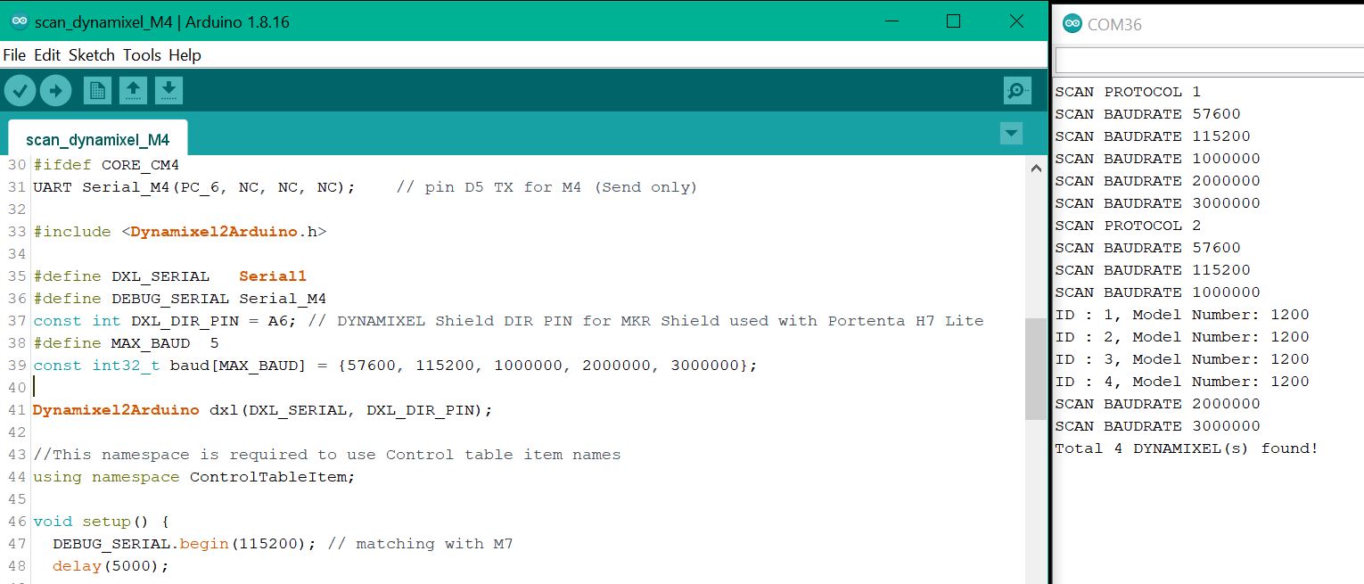
You can see that the original “scan_dynamixel.ino” sketch is virtually unchanged. The only issue was that the Serial Monitor is not available to the M4 core, so a “round-about” solution was created using the tightly coupled UART Ports Serial_M7 and Serial_M4 via Pins D5 and D6.
Well, did it work? Yes and No. Below is a screen capture of a good run
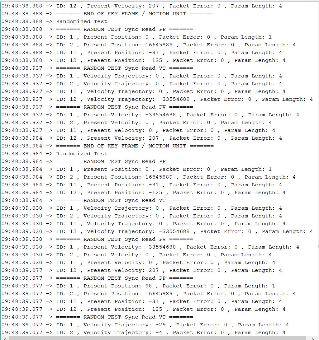
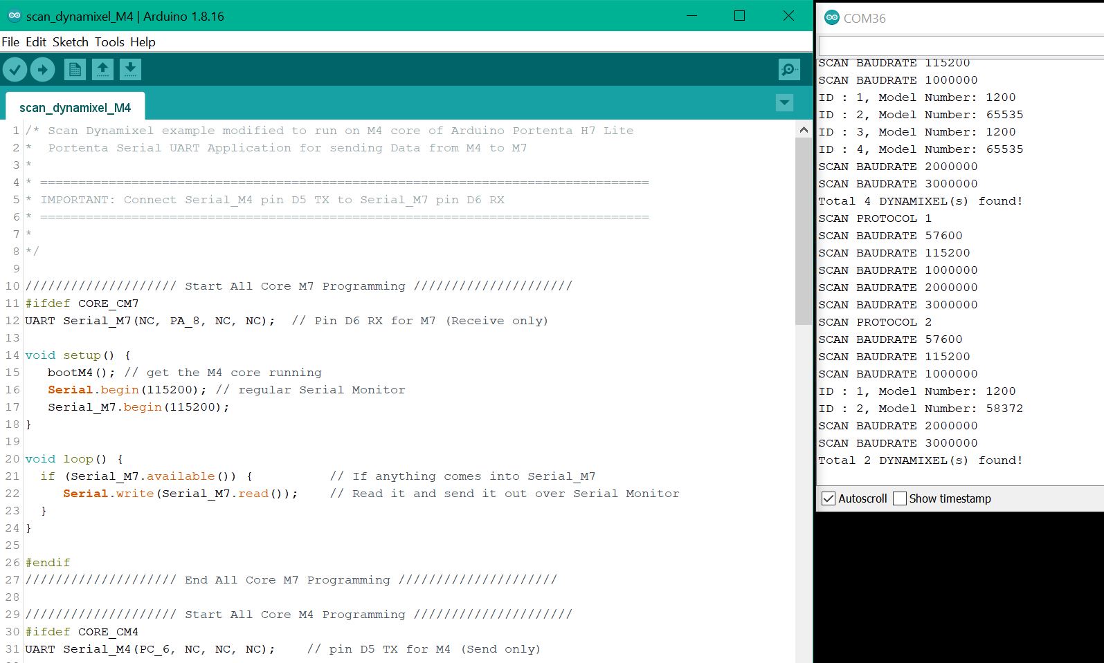
But sometimes, I would get bad runs
-
My SPI Pixy2 camera could not be made to work on the M4 core.
-
My I2C VL53L5CX ToF imager gave me 1 reading and got locked up.

So, it looks like that only the M7 core can be put into practical uses at present.