Dynamixel XC330-T181 jittering around fixed goal position

DYNAMIXEL Actuator

XC330-T181-T

Issue Description

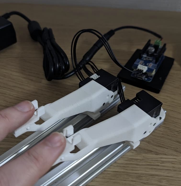
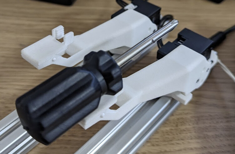
I am building a compliant robot with multiple XC330 motors. For this example, I have two XC330-T181-T motors, each with an 8-cm long nylon arm attached (lightweight, approximately 10-15 grams). I am using DynamixelShield for Arduino MKR with an MKR Zero.

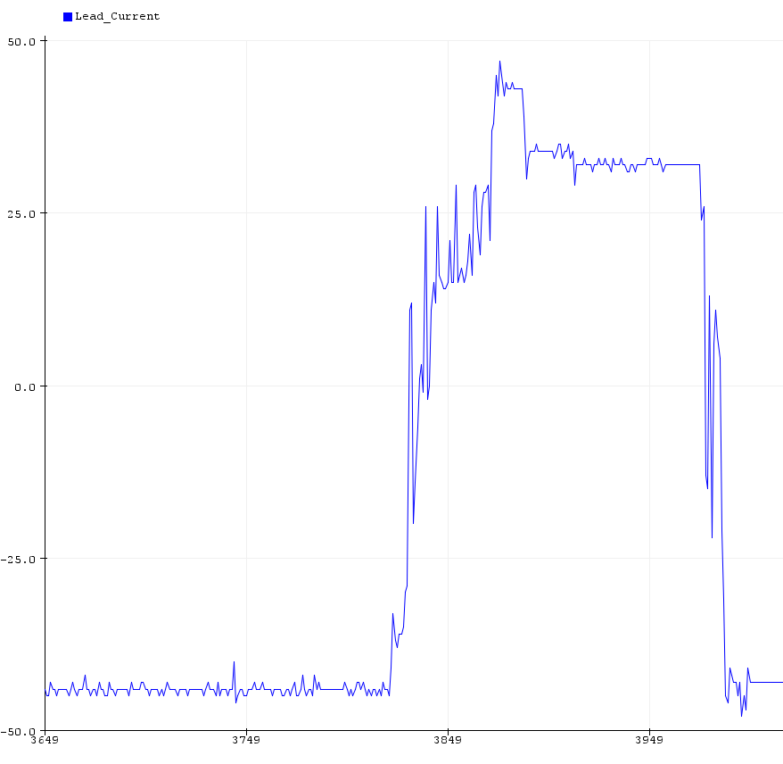
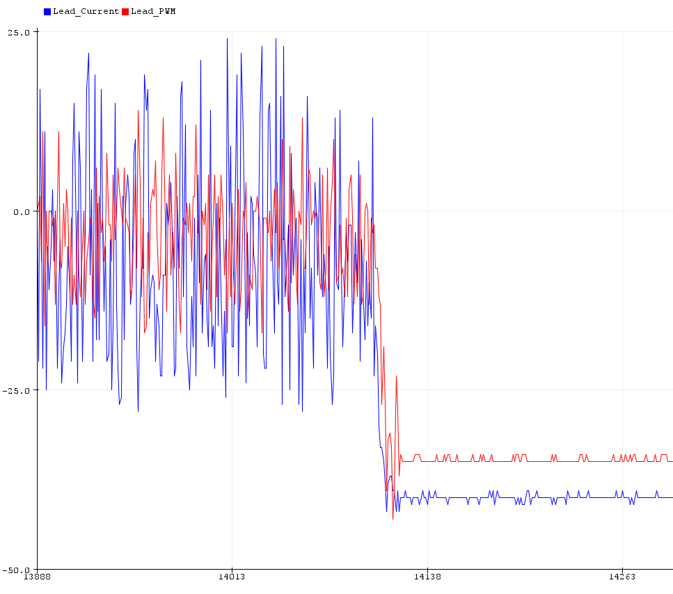
The first motor (Lead) is in current-based position mode (OP_CURRENT_BASED_POSITION) with goal current set to ~200mA (dxl.setGoalCurrent(DXL_ID_LEAD, 200)) and goal position to horizontal. This makes a compliant arm that can easily be pushed with a finger and returns to the horizontal position when the load is removed. There is no jitter in the first motor (Lead) operation.

The second motor (Follow) is in position mode (OP_POSITION), with PID roughly tuned for a fast response (P=3000, I=100, D=1000). Then, I have the second motor follow the first one:
lead_pos = dxl.getPresentPosition(DXL_ID_LEAD, UNIT_DEGREE);
dxl.setGoalPosition(DXL_ID_FOLLOW, lead_pos, UNIT_DEGREE);

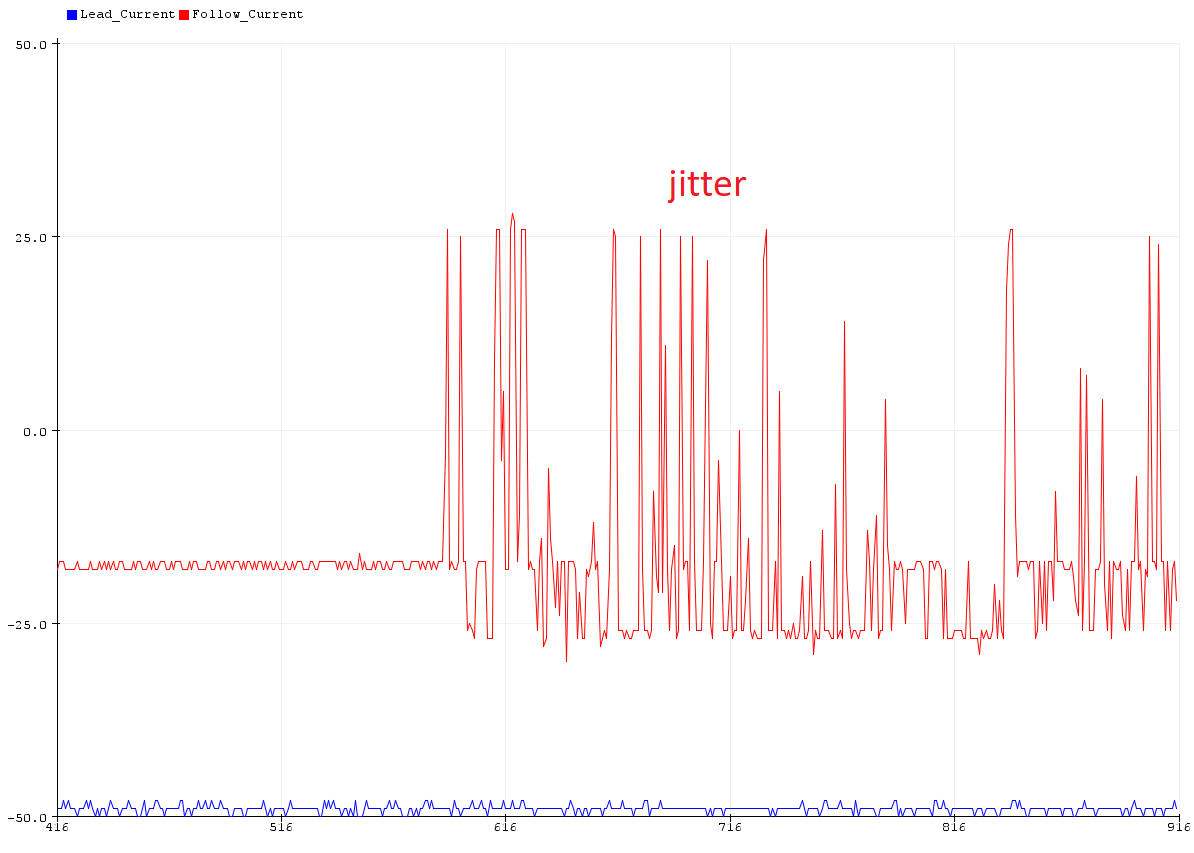
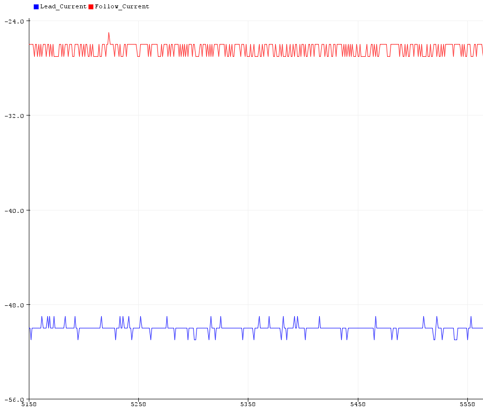
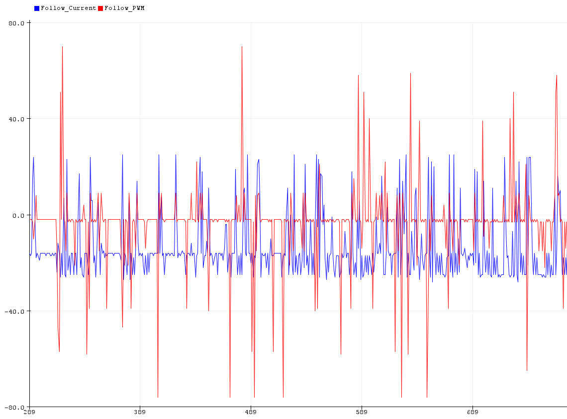
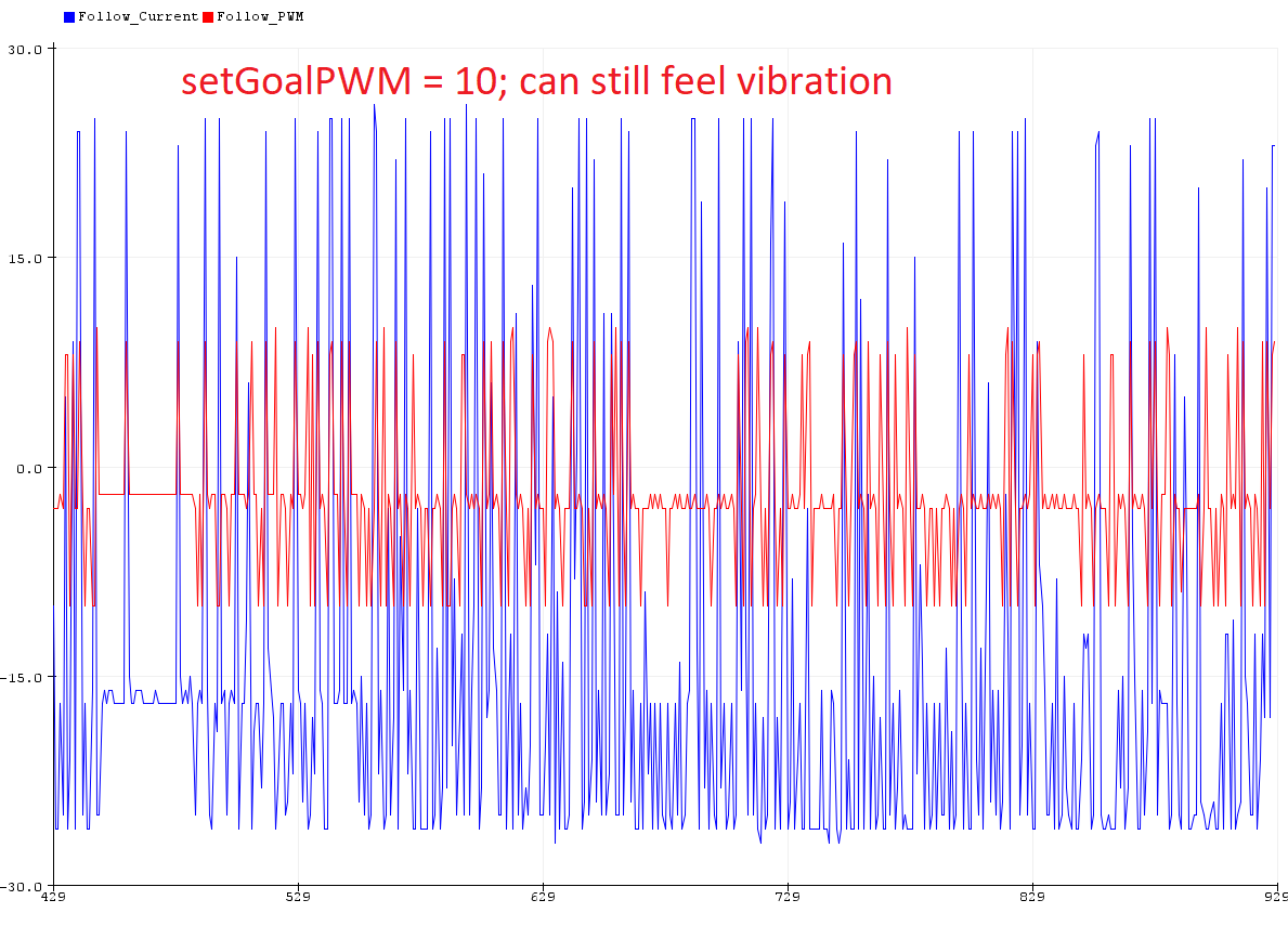
This works fine, but the Follow motor has an occasional jitter/dither to it, even when GoalPosition is kept constant. You cannot visually see the jitter, but you can hear it and physically feel it as a vibration when your finger is on the nylon arm.

I tried setting dxl.setGoalPosition(DXL_ID_FOLLOW, horizontal_pos, UNIT_DEGREE); and the same issue occurs. Resetting PID to default settings (P=900, I=0, D=0) does not change the jitter.

I can remove the jitter by setting the Follow motor to OP_CURRENT_BASED_POSITION and setting goal current lower (e.g. 200mA, like the Lead motor). This requires some retuning of the PID (P=3000, I=100, D=3000, increasing D was required to make it stable), but then the response is not as snappy.

I have two XL330-M288-T motors for prototyping that I set up in a similar configuration. The Follow XL330 motor does NOT exhibit any jitter. However, I’m not sure if this is due to the gearing (181 vs 288) or because of the inherent lower power (the XL330’s are just running off the 5V from Arduino USB).

Therefore, I’m wondering if this is due to the gearing of the motor (181 vs 288), the current supply, or something else I’m missing. I can use the XC330-T288 instead, but I really like the gearing of the T181 for compliance so far (much easier to get movement started).

One solution is to keep the Follow motor in OP_CURRENT_BASED_POSITION and increase the goal current only when large changes in goal position are detected, but I’m worried I wont be able to find a PID tuning that’s both snappy and stable if the goal current changes dynamically.

Thanks for reading, any suggestions/help are greatly appreciated!

Additional Information/Attachments

I’ve included a picture of my setup for clarity.

My first guess as to what is causing this behavior is to second your suggestion that it has to do with the higher voltage and lower gear ratio being inherently harder to stabilize. I’ve had problems in the past getting stable PID tunes for XC330 actuators due to their tendency for overshooting goal positions when trying for high speed responses.

Regarding your proposed solution of changing the goal current in response to large goal position changes, you may be able to keep a quick and stable response profile if you also adjust the PID settings dynamically. Having 2-3 sets of goal currents and PID tunes can allow you to select the most appropriate motion profile for motion depending on the delta for that particular motion.


I’ve also got a few additional suggestions for troubleshooting that you didn’t mention in your post that might identify if there is some hidden issue causing this:

  • If you swap the lead and follower motors does the jittering still occur? That would be a quick way to check if it’s an issue with that specific motor.
  • Does using raw position units to sync the follower produce the same behavior?

Thanks for the quick reply!

  • If you swap the lead and follower motors does the jittering still occur? That would be a quick way to check if it’s an issue with that specific motor.

Forgot to mention, swapping the roles of the motors also swaps their behaviors. So, not specific to that one motor.

  • Does using raw position units to sync the follower produce the same behavior?

The issue occurs even if I don’t try to sync lead/follower (for example, just set goal position to horizontal once and never update it). So the units shouldn’t matter.

I’ve done some more testing and found that there is more difference between Position-based control and Current-based position control than I naively assumed.

I sort-of assumed that setting:

dxl.setOperatingMode(DXL_ID_FOLLOW, OP_CURRENT_BASED_POSITION);
dxl.setGoalCurrent(DXL_ID_FOLLOW, 910); // maximum current limit

would result in similar behavior to OP_POSITION, but this is not the case.

I took a closer look at the current and PWMs to see what’s going on.

This is the typical behavior where the lead motor stays still and the follow motor has a jitter:
image

Applying a light weight to the end of the Follow arm removes the jitter:
image
image

In fact, the Lead motor (current-based position) also doesn’t like to sit in low current. It has sort of a ‘dead zone’ where if you push it, it will happily move to either end. This ends up being around +25 to -50mA (the weight of the arm pushes it in the -mA direction):
image

I can force the Lead motor (current-based position control) into a low current state (by physically holding the arm in a specific position), so that it hangs out around 0mA. It doesn’t like this, and dithers back and forth - the PWM is active, too. But I don’t feel any vibration/jitter:
image

Checking the Follow motor (position control) in the jittering state:
image

Interestingly, if I clamp the PWM for follow motor, it STILL physically vibrates (vibration feels dampened) at low current. Also, the motor is barely responsive (as expected by clamping the PWM).
image

So, it appears that the motor doesn’t like to sit in low current (+/- 25mA) and will dither to avoid this.

In current-based position control, it will either (a) allow the motor to rotate into a steady-state outside of this range, or (b) lightly dither around the low current point without making a noticeable vibration.

In position-based control, it will dither between ±25mA until it moves outside of that current range. Although, sometimes it will just hang out at, say, -18mA without jittering, but any sort of light touch on the arm can set it into jitter mode. The PWMs are much jumpier in the position-based control dithering vs. the current-based position control mode.

The response of the motor is always snappier in position control mode vs. current-based position control, so I think the solution of tuning the goal current and PIDs in real-time isn’t the ideal solution. Simply adding a bit more weight to the arm solves the jitter at rest, but the behavior could still occur at other points of operation.

There are a few things I can’t figure out how to try/aren’t available on DynamixelShield or the XC330? I see, for example CW_COMPLIANCE_SLOPE but it isn’t on the XC330; and there’s also a PWM Slope(62) in the documentation but no way (that I can see) to set it on DynamixelShield/Dynamixel2Arduino… I guess I am wondering if the different dithering strategies are just inherent to position-based/current-based position control, or if there is any way to tweak them with some configurations.

Thanks again!

There isn’t a premade function to modify the PWM Slope in the Arduino SDK, but you can modify the value through Arduino using the generic writeControlTableItem() function to write to register 62.

I’ve also reached out to our HQ engineers to ask about the specifics of this behavior in low current situations, to see if we have any official documentation on it.

Hi Jonathan, any luck finding a cause of this with the engineering team?

I tried a couple other things. First, I checked if the velocity or acceleration profiles were modified in OP_CURRENT_BASED_POSITION, but they are set to default.

Next, I checked what the PID gains were for OP_CURRENT_BASED_POSITION by default. I assumed they were P=900, I=0, D=0 as the XC330 default. But, they’re actually P=400, I=0, D=0. I set the Follow motor to these values, but it still jitters.

Finally, I tried to see if something was up with PWM Slope(62) but I got stuck because I couldn’t confirm that reading or writing by the raw ID (e.g. (62)) was actually working.

For example, I used POSITION_P_GAIN (84) as my test:

uint8_t custom_table_id = 84;
// ...
DEBUG_SERIAL.print("FOLLOW_P_GAIN:");
DEBUG_SERIAL.print(dxl.readControlTableItem(POSITION_P_GAIN, DXL_ID_FOLLOW));
DEBUG_SERIAL.println();
DEBUG_SERIAL.print("FOLLOW_P_GAIN_RAW:");
DEBUG_SERIAL.print(dxl.readControlTableItem(custom_table_id, DXL_ID_FOLLOW));
DEBUG_SERIAL.println();

From serial monitor:

FOLLOW_P_GAIN: 400
FOLLOW_P_GAIN_RAW: 3057

So I tried just doing:

DEBUG_SERIAL.print("POSITION_P_GAIN:");
DEBUG_SERIAL.print(POSITION_P_GAIN);
DEBUG_SERIAL.println();

From serial monitor:

POSITION_P_GAIN: 43

And rerunning the first code with custom_table_id = 43 accurately gives me the P_GAIN.

I tried a few others:

TEMPERATURE_LIMIT: 12 // datasheet:  31
VELOCITY_I_GAIN:   42 // datasheet:  76
GOAL_PWM:          55 // datasheet: 100
MOVING_STATUS:     82 // datasheet: 123

So I realized that (62) does not work for PWM Slope, I actually have to use the raw index from ModelControlTableInfo_t in actuator.cpp. For example, TEMPERATURE_LIMIT is the 13th item on the list (index by zero = 12).

Unfortunately, PWM Slope does not exist in the Arduino control table. Is there any way that I’m missing to directly address by the control table ID (e.g. (62))?

I managed to manually check and set PWM Slope using the dxl.read() and dxl.write() functions from the base library API.

#define PWM_SLOPE_ADDR     62
#define PWM_SLOPE_ADDR_LEN 1
#define TIMEOUT 10

uint8_t returned_pwm_slope_follow = 0;
uint8_t new_pwm_slope = 10;

dxl.write(DXL_ID_FOLLOW, PWM_SLOPE_ADDR, (uint8_t*)&new_pwm_slope, sizeof(new_pwm_slope), TIMEOUT);
dxl.read(DXL_ID_FOLLOW, PWM_SLOPE_ADDR, PWM_SLOPE_ADDR_LEN, (uint8_t*)&returned_pwm_slope_follow, sizeof(returned_pwm_slope_follow), TIMEOUT);

In the end, I found that PWM Slope = 255 by default in OP_CURRENT_BASED_POSITION, and confirmed that setting a new value (e.g. PWM Slope = 10) indeed changed the behavior of the motor (making it less responsive). So, that doesn’t explain the behavior.

I realized that for my application, I will need to switch the behavior of motors on the fly (for example, switching the lead and follow motors), so I would like to keep all motors in the OP_CURRENT_BASED_POSITION mode, adjusting the gains and goal current as needed.

So, my last outstanding question is why the behavior of the motors is different in OP_POSITION and OP_CURRENT_BASED_POSITION, when no goal current is set (can go up to maximum). I tested a bunch of different PID tunings and found workable gains of:

OP_POSITION:

  • P = 3000
  • I = 100
  • D = 1000

OP_CURRENT_BASED_POSITION:

  • P = 3000
  • I = 100
  • D = 3000

In Current-based Position, the motors exhibit more overshooting behavior, but no jittering. Anyway, it is workable now, and I hope this info will help others who try to set up a similar control mode!

1 Like