[lerobot_ojw] STL Files Are Now Public!
I’ve just released the complete STL dataset for the lerobot_ojw project. The software part is still under development,
but you can now explore:
All individual part STL files
Full robot assembly previews
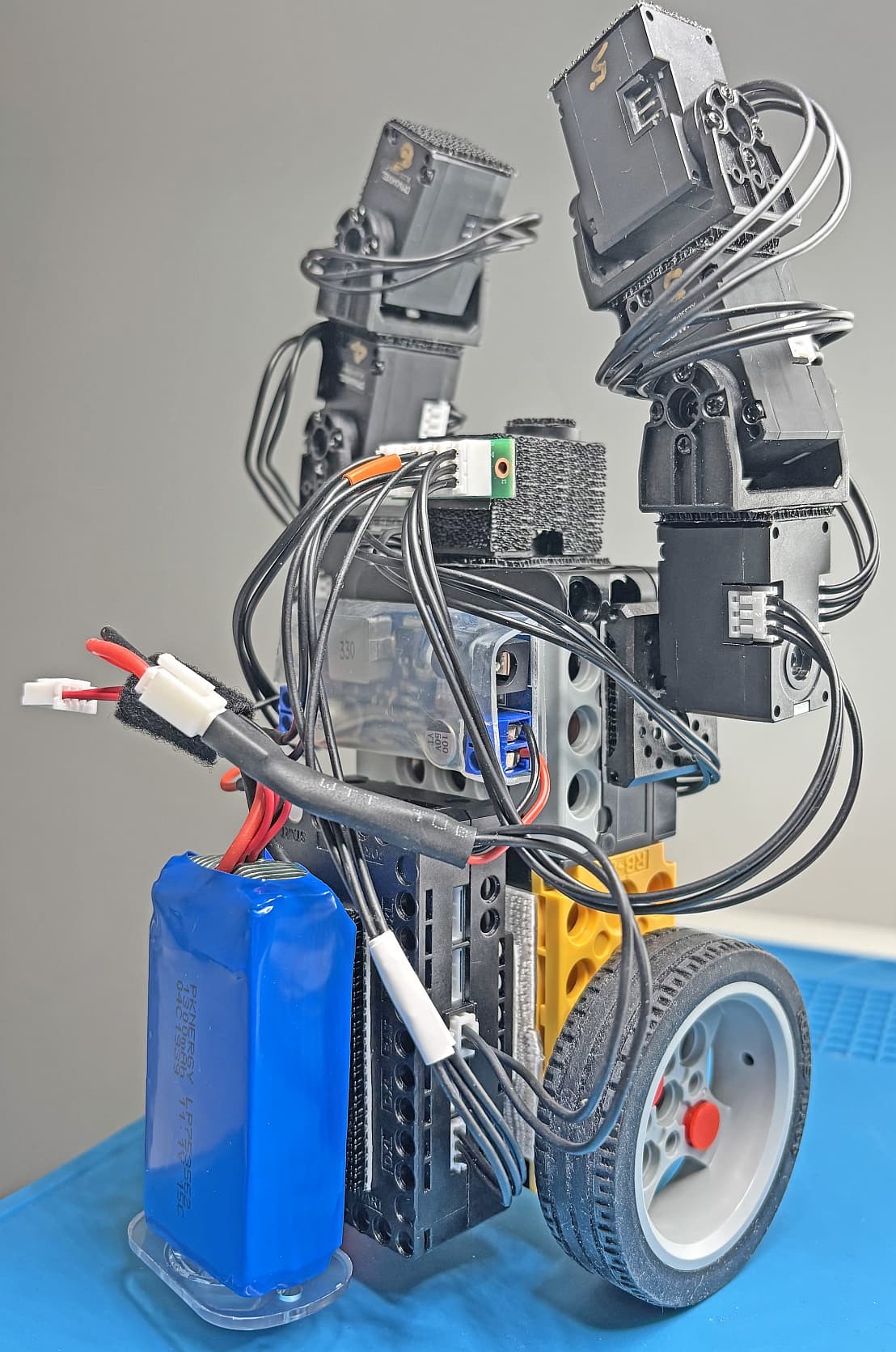
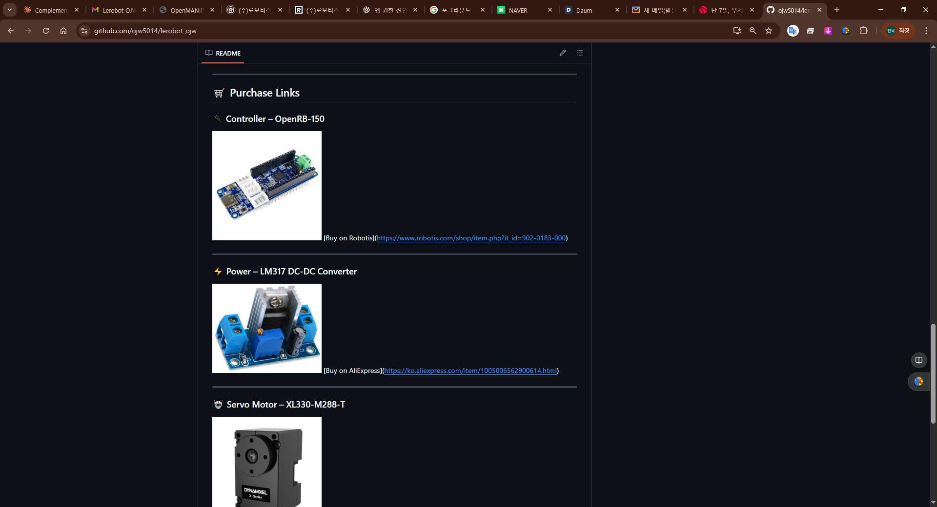
Organized component list with prices and purchase links Check it out on GitHub:
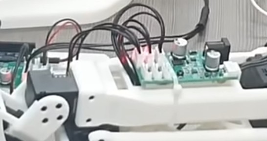
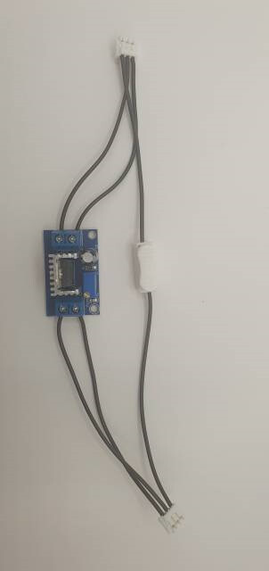
It looks like a Voltage Converter Module (12V to 5V) (+ Common DATA line) but it also has 6 X3P connectors built-in to it. This is a very handy module to use. Did you make your own or is that one on sale in South Korea only? If it is a ROBOTIS product, I hope that ROBOTIS would release it soon to all users! I do get tired of creating all these ad-hoc contraptions like shown below every time that I need to do mixed-voltage DXL connections and programming.
The board used in the video you asked about is one that another user developed themselves using my source code, whereas the board I used was purchased online. The materials are linked here: GitHub - ojw5014/lerobot_ojw.
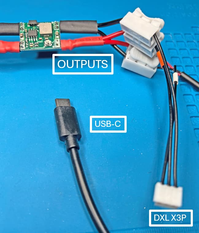
To wire it up, connect VCC and GND to the input, then connect VCC and GND in the same way to the output, and finally connect the data cable directly.
This board was developed by kr-lee-sh, a ROBOTIS engineer. He created it as a personal project and has released it under an open‑source license. You can find all the files and documentation here:
The LM317 works well for me. But one caution for the new user is that the LM317’s heat sink will get hot, so no finger and no wire should touch it when it is operating!
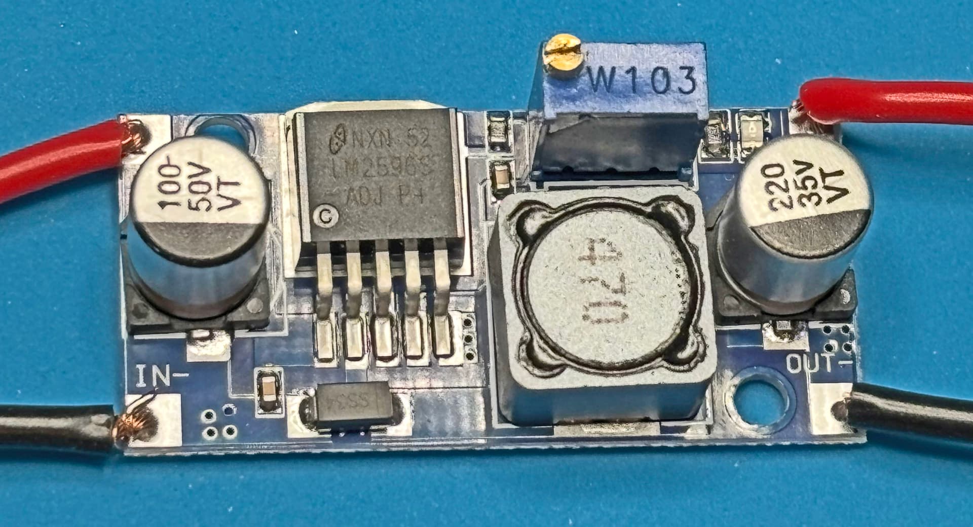
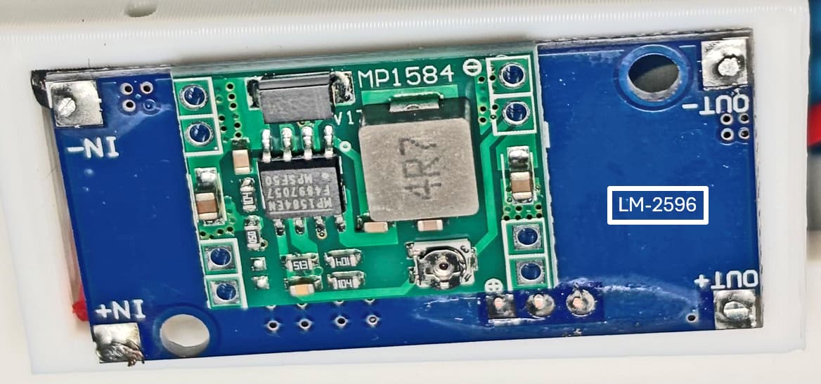
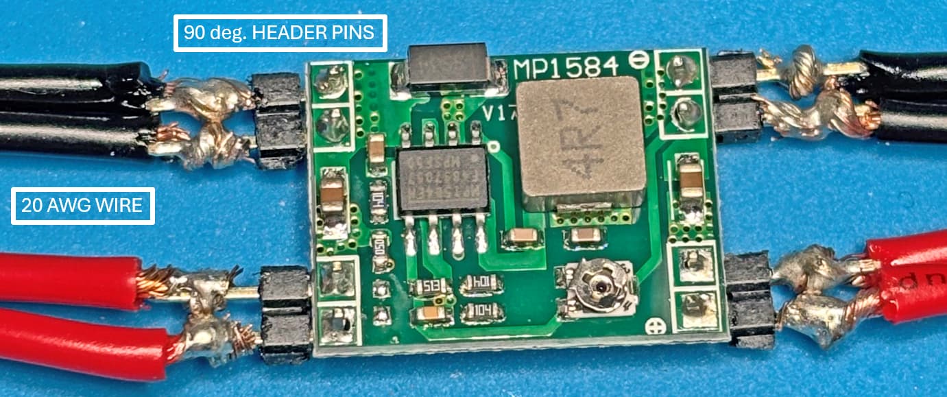
I happen to have a stash of LM2596 based Voltage Converters and they do not have Terminal Blocks on board. So I soldered some 20 AWG stranded wire to this module
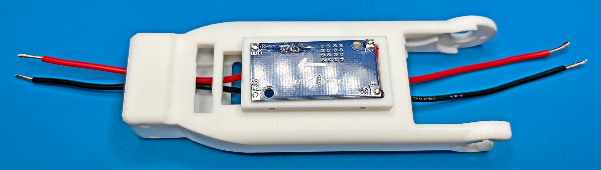
Your design has a cap to cover this area, and I can still use this cap but I will have to tape it down or use a twist tie over the forearm to keep it in place, as the screw holes won’t line up anymore!
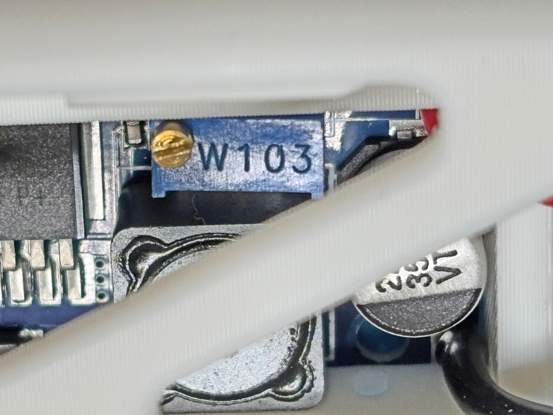
This LM2596 can be adjusted from the other side of the forearm
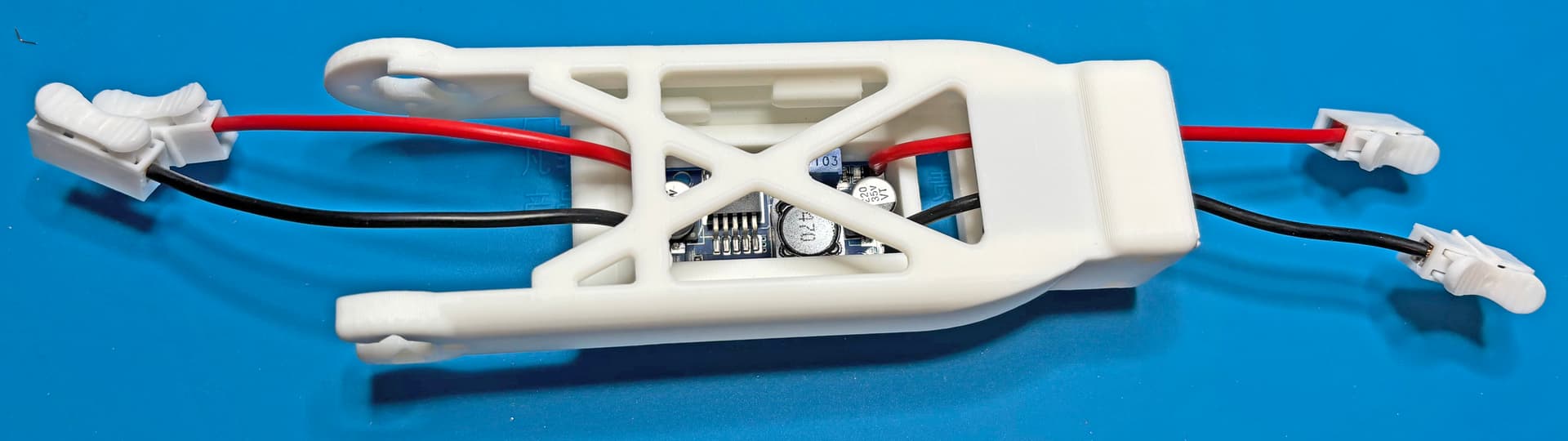
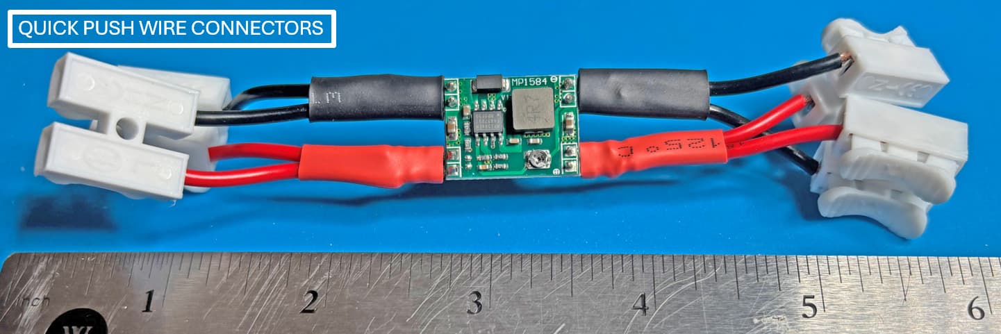
Later during the actual assembly, I plan to cut the wires to fit and then use these Push Wire Connectors to connect with the Standard X3P cables as previously shown in your design.
Hello! I found your build process really interesting. The product I used was this one: 404 page chose it because it proved the most reliable for my setup. How has your DC‑DC board performed so far? In my experience, I ran into two issues: first, the power would cut out when subjected to a sudden strong impact; second, I saw a lot of noise on the data lines during uploads, which led to a high rate of transmission failures. I hope yours works smoothly, and I’ll be giving it another go myself soon.
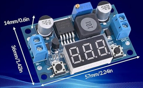
For my situation, I am not working 100% on your arm yet, as at present I am working on a semi-humanoid based on an RB-88 chassis as shown in my previous picture. It uses 7 XL-330-M228 (2 arms with 3 servos each + 1 neck servo) and the LiPo battery from the Engineer kit. So far, I have interfaced my system with the LM-317 and LM-2596, and only the LM-317 heats up too much on me during operation. From what I read about the LM-317, it is a Voltage Regulator, meaning that it suppresses the electrical power between 12V and 5V and changes it to thermal energy via the heat sink, this is why its heat sink gets so hot (also meaning that it will fail faster). The LM-2596 does convert the voltage differently at about 95% efficiency, that’s why it does not get hot during use: this also means that I am getting more play time out of my LiPo battery when using LM-2596.
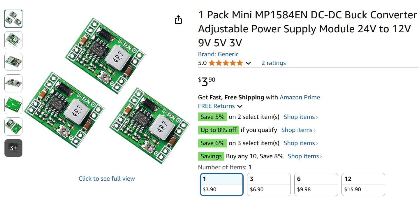
Yesterday, Kr-Lee-Sh mentioned that his board uses the MP-1584 chip - which I had never used before. Digging around Amazon, I found that they are available in the USA too at very reasonable costs.
Up to 3A like the LM-2596, but with a slightly less efficiency of 92%, but its size can be much smaller than the LM-2596, its module measures only 25.5 mm by 17.2 mm! I already ordered some to try out. So stay tuned.
By the way, if you are interested in the semi humanoid project (also named Gladiator), I got a post for it on STEAMCUP: basically Motion Programming from the PC using DXL-SDK.
You can notice that each pole has 2 wire connections. So first I soldered 90 deg. header pins on them, then soldered in 20 AWG wires (luckily, my sloppy soldering skills did not impact the final functionalities )
Yes, you can say that I am partial to Spring Push Wire Connectors, but there are also other operational reasons for my typical uses of Voltage Conversions:
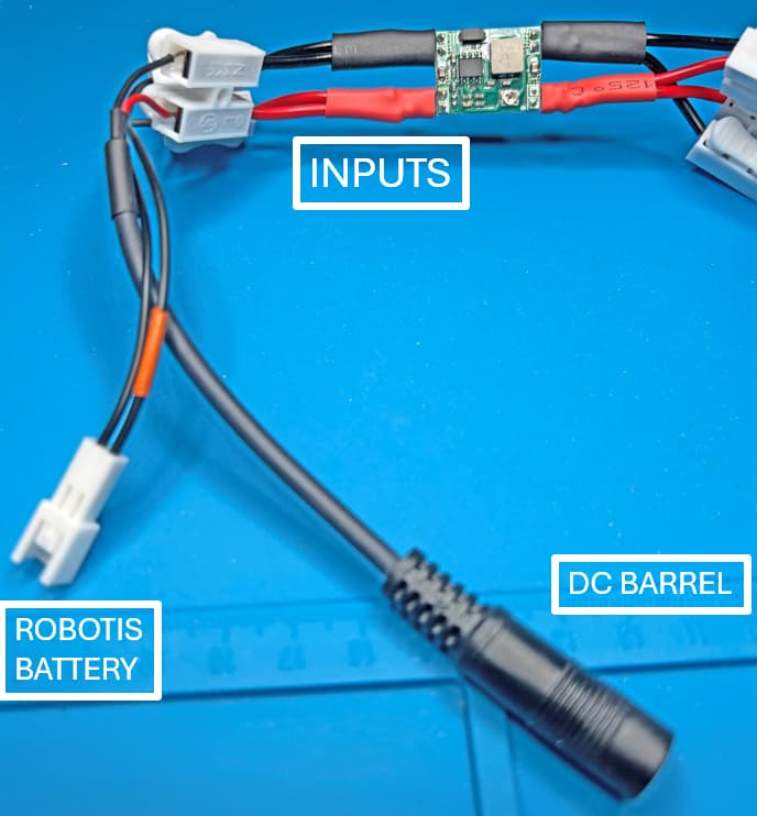
For INPUTS, sometimes I need to interface with ROBOTIS BATTERIES or DC BARREL PLUGS.
I did some preliminary check on Voltage Conversion 12V to 5V, and my “device” worked fine. The Potentiometer module on the MP-1584 is way more sensitive than the one used on LM-2596.