06/01-07/11
The BANSHEE UAV research team from the College of Engineering at California State Polytechnic University, Pomona (Cal Poly Pomona) is excited to announce our renewed partnership with ROBOTIS for the summer. This collaboration will center on the integration of ROBOTIS’s advanced Dynamixel technology into our work. We extend our sincere gratitude to ROBOTIS for their invaluable support and invite the community to provide feedback on our developments over the coming months.
This project is being led by Clay Kim and Joshua Carrasco. While we initially planned for biweekly updates, our new leadership team has been focused on establishing a strong foundation for the project since our start in early June. We are now pleased to share a comprehensive update on our progress.
Project Conception: From Idea to Reality
Our initial brainstorming led to two distinct project ideas:
- Crane-like Vehicle: A remote-controlled car base equipped with the ROBOTIS OpenManipulator-X platform.

Figure 1.1
- Bipedal Humanoid Robot: A humanoid robot powered by multiple ROBOTIS Dynamixel XM motors.
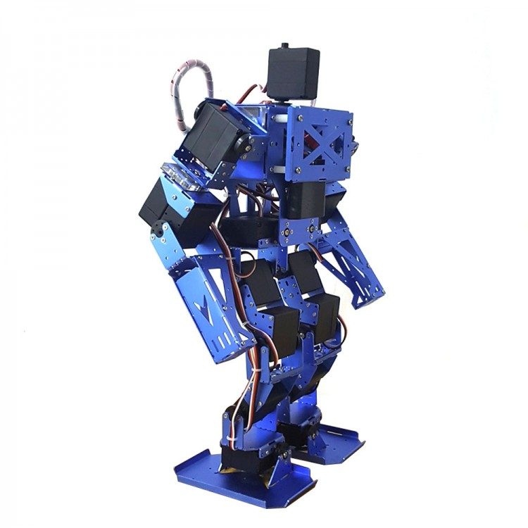
Figure 1.2
After consulting with Jonathon, a representative from ROBOTIS, we decided to pursue option 1, the crane-like vehicle. This project serves as a compelling proof of concept with real-world applications.
Project Goal: Autonomous Object Manipulation
Our primary objective is to develop a fully autonomous RC vehicle with an integrated robotic arm. The vehicle will utilize LiDAR for navigation and a camera mounted on the arm for machine learning-based object recognition and manipulation. While our timeframe limits the scope of this project, we believe it has the potential to be applied in scenarios such as automating warehouse and construction tasks.
Team Structure and Initial Progress
We have assembled a talented team of 10 students, divided into three specialized subteams: Mechanical, Electrical, and Software.
Mechanical Team (4 members):
- Researching a system design that accommodates LiPo batteries, a Jetson Nano microcontroller, motors, and the robotic arm.
- Collaborating with the Electrical Team to finalize the parts list.
- Designing a custom chassis that meets all design constraints.
Electrical Team (3 members):
- Evaluating ESP-NOW and nRF communication protocols for the remote controller.
- Researching power distribution and LiPo battery safety.
- Determining the necessary components for optimal power distribution.
Software Team (3 members):
- Installing ROS2 on the Jetson Nano microcontroller.
- Researching inverse kinematics for precise control of the ROBOTIS motors.
- Investigating SLAM (Simultaneous Localization and Mapping) with LiDAR for autonomous navigation.
- Developing ESP communication for wireless remote control during the initial testing phase.
Moving Forward
Following the initial phases of team integration, preliminary research, and component procurement, the project has progressed to focused work on more detailed and specific technical aspects of the project.
A significant anticipated challenge is the initial assembly of the RC car platform. Precision is critical, as any errors during this phase could lead to considerable project delays. To mitigate this risk, team leads will provide closer oversight during the assembly process. They will take a more direct role in supervising the sub-teams to ensure every component is integrated correctly and all work is performed to specification.
Over the course of the month of June the team has made significant progress across all sub-teams. This report outlines the key accomplishments, tasks undertaken, and challenges encountered during this period.
- Mechanical Team: The mechanical team has successfully developed a detailed CAD model for the first layer of the RC car chassis, shown in Figure 2.1. Concurrently, they have designed several 3D-printed components, that can be seen in Figure 2.2-2.3, to enhance the stability of the robotic arm.
- Electrical Team: The electrical team focused on critical power and control systems. They have completed the design for the custom PCBs for power management, shown in Figure 2.4. Additionally, they have designed a remote controller, which will provide integrated control over both the RC car and the robotic arm.
- Software Team: The software team has been configuring the Jetson Nano microprocessor, the central processing unit for the project. This foundational work is crucial for the future implementation of the robotic arm’s inverse kinematics, the integration of the custom remote controller’s functionality, and the autonomous navigation for ROS2 SLAM.

Figure 2.1 CAD Model first chassis layer
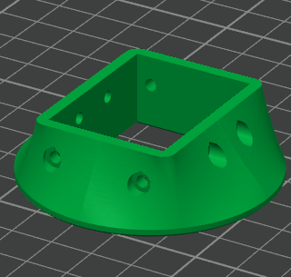

Figure 2.2-2.3 3D printed mounting bracket
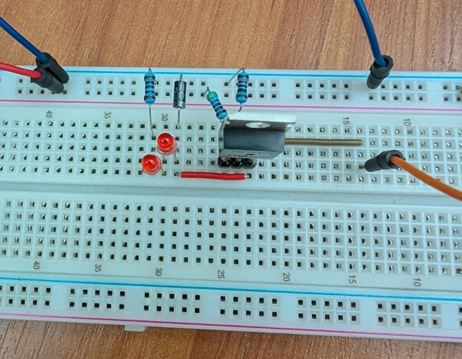
Figure 2.4 Power path circuit diagram Figure 2.5 Prototype circuit
07/14-07/25 Update
Over the past two weeks, the team has made satisfactory progress on the remote-controlled car project. With less than a month remaining before the deadline, the car has not yet been fully assembled due to specific chassis build constraints and 3D printing times. As a result, both the software and electrical teams were faced with bottlenecking within the respective teams. To combat this all teams have been working hard to continue with the project and have completed other tasks while we finish assembling the chassis.
Mechanical Team
The mechanical team has made significant progress following the arrival of the ordered components, coordinated through our budget overseer. Over the past two weeks, we developed a comprehensive schematic of the chassis on SolidWorks (Figure 3.1). Team members collaborated by dividing the design tasks, each working on a specific section before integrating the parts into a final assembly.
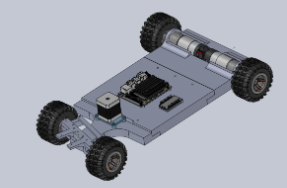
Figure 3.1: Full Chassis Schematic
During the 3D printing phase, we encountered a limitation: our Bambu Lab X1 Carbon printer could not accommodate the full chassis in a single print. To resolve this, we divided the design into three sections (Figure 3.2), enabling us to print the entire chassis into 3 parts: front, middle, and rear.
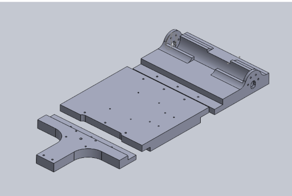
Figure 3.2: Chassis Broken Up
Despite initial hurdles, we successfully printed the front portion of the chassis—featuring Ackermann steering (Figure 3.3.1)—and the mount for the stepper motor that controls the steering mechanism (Figure 3.3.2). While we did not complete all prints within our original two-week goal, these outputs represent substantial progress.
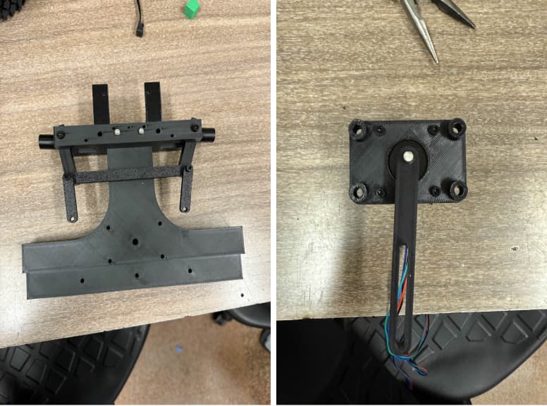
Figure 3.3.3-2: Front Chassis and Stepper Mount
Software Team
The software team faced several challenges while configuring the Jetson Nano. Initially, we used the JetPack 6.2 environment, which caused compatibility issues with Gazebo and prevented integration with our LiDAR system. We resolved this by switching to Ubuntu 22.04, which restored Gazebo functionality. Consequently, we reinstalled ROS and resumed testing the OpenManipulatorX. We also upgraded the robotic arm by adding a sixth motor, enhancing wrist mobility with improved claw rotation. Although we were unable to install Dynamixel Wizard on the Jetson Nano, we proceeded with testing using an external computer.
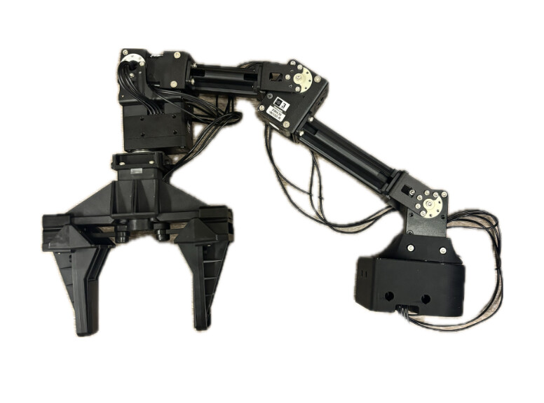
Figure 4.1: OpenManipulatorX
In terms of kinematics, we are in the process of obtaining complete car dimensions to accurately model the robot. The current URDF file is misaligned due to incorrect reference axes at several joints. This will require modifications to the SolidWorks model and the generation of a revised URDF using the SW2URDF plugin. These adjustments are essential for deriving accurate inverse kinematics equations via IKPy. Additionally, we are exploring how to integrate the Intel depth-sensing webcam into the inverse kinematics pipeline, which will require implementing appropriate coordinate and kinematic transformations.
Meanwhile, one of our co-leads has initiated the development of a low-fidelity AI model using Roboflow to track a green 3D-printed cube. Initial results showed inaccuracies (Figure 4.2.1), but through several refinements, we achieved a much higher level of precision (Figure 4.2.2).
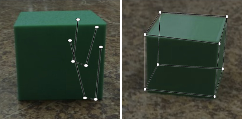
Figure 4.2.1-2: Pose Estimation for Green Cube
Although the robotic arm’s code is complete, we have not yet had the opportunity to test it due to time and hardware constraints. We are currently awaiting the full assembly of the remote controller to proceed with testing. The code for the ESP-32 microcontrollers has also been prepared. All code developed thus far has been published to our
GitHub repository: GitHub - galgim/ROBOTIS_INTERNSHIP_SUMMER_2025
Electrical Team
The electrical team has encountered fewer direct challenges; however, their progress is largely dependent on the availability of a physical platform provided by the mechanical team. In the meantime, we have successfully built a prototype remote controller. We soldered the joysticks and potentiometer encoders onto a protoboard for initial testing (Figure 5.1), and the wiring layout is shown in Figure 5.2.
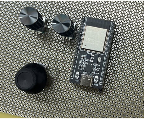
Figure 5.1: RC components
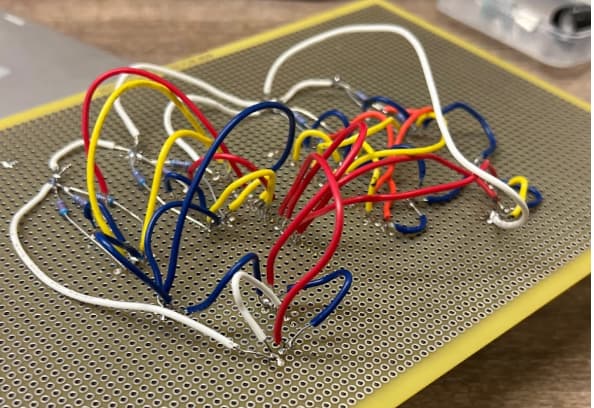
Figure 5.2: RC wiring
Additionally, a team member designed a LiPo battery charging circuit for the RC car. Using a 600mAh battery for testing, the prototype circuit charges up to 4.2V using a constant current (Figure 5.3). The complete circuit schematic is presented in Figure 5.4.

Figure 5.3: LiPo charging test circuit
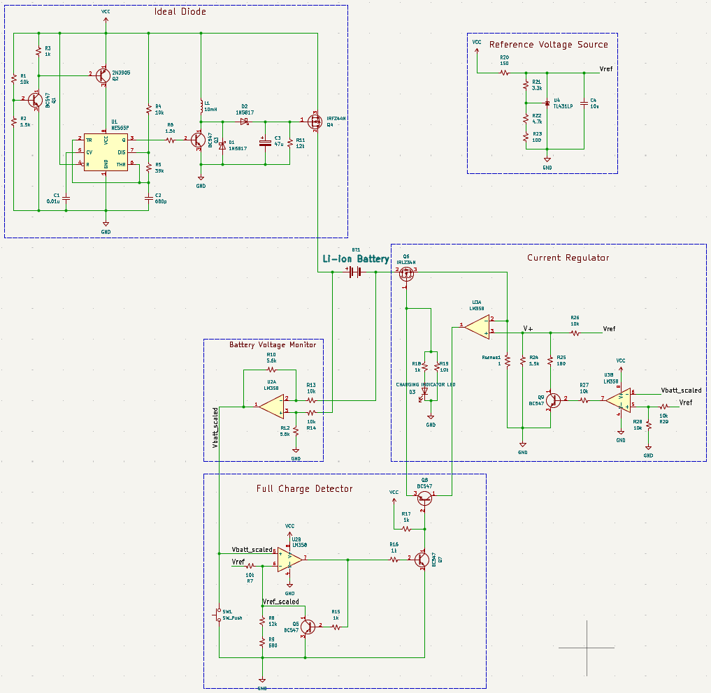
Figure 5.4: Charging Circuit Schematic
Next Steps
With only two weeks remaining in the summer term, our final goals are as follows:
-
Complete the assembly of the RC car
-
Mount the OpenManipulatorX onto the chassis
-
Connect all electronic components to LiPo batteries
-
Set up ESP-32 communication between the Jetson Nano and remote controller
-
Record a demonstration video of the RC car in motion, successfully picking up the green 3D-printed cube
Overall, each team has made meaningful progress toward the project’s completion. We remain optimistic about achieving our final objectives within the remaining timeframe.
*
*
*
07/28-08/08 FINAL UPDATE
Over the final two weeks, the team has successfully implemented most of the core functionalities. We have established a working connection between our remote controller and the OpenManipulatorX, and have also verified the operation of the drive motors. All components are now drawing power correctly from the LiPo batteries. A notable success was a demonstration where the arm was able to pick up a green cube. The only feature we were unable to complete was connecting the drive and steering motors to the controller for remote operation.
Mechanical Team Update
The mechanical team was able to bring our design schematics to life and have a fully 3D printed chassis created, Figure 6.1. As we mentioned in the previous update we were not able to print the whole chassis at once so we went ahead and split it up into 3 parts: the front, middle, and rear. The main concern with this way of printing was the rigidity of the whole system but once we put everything together it was very solid.
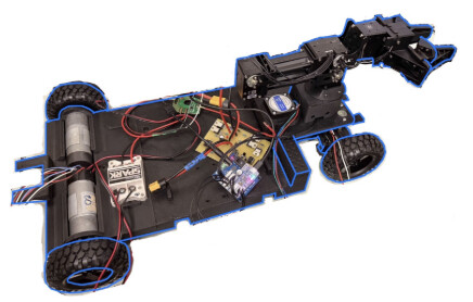
Figure 6.1: Full Build
One addition we added to the base chassis was mounting a plate for our robotic arm, Figure 6.2.1. We created it with the idea to be supported on top of our steering bar and be both clamped around our stepper motor, Figure 6.2.2, and have support walls with holes on it for any future mounting we could potentially use it for.
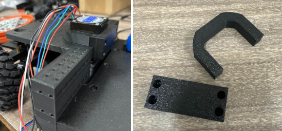
Figure 6.2.6-2: Arm Mounting Plate and Support Clamps
One hurdle we ran into with mounting our arm onto this plate was that the screws prevented the arm from sitting flush so we cut out some inserts to allow the arm to fit, Figure 6.2.3-4. We also ran into the problem of our potentiometers being in the way of the plate so we had designed the plate to have holes so that the plate could fit on top of it.
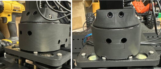
Figure 6.2.3-4: Arm mounted on plate
Software Team Updates
The software team was able to establish wireless connection between the controller and the car, allowing for the OpenManipulatorX to move based on encoders on the controller. There are joysticks on the controller that will control the dc motors and stepper motor in the near future. As we had completed most of the code a while ago, these two weeks were more for testing if the code really worked since most of our hardware components had just been completed. For the most part, the arm movement code was solid, but reading values from the ESP on our controller was posing to be a problem. It was very slow at times and the code would not run at seemingly random times, but after some improvements in the code, the speed has drastically improved and there are no problems ever running the code.
Arm movement test video: https://www.youtube.com/watch?v=vIvnv64yGHA
Claw gripping test video: https://www.youtube.com/watch?v=vIvnv64yGHA
The final demonstration video for the arm is shown on a gif below on Figure 7.1
Figure 7.1: OpenManipulatorX testing with wireless controller
The arm was successful, but when we were going to test simple movement on the DC and stepper motors, we made a mistake and shorted our battery switching circuit in Figure 2.2, so unfortunately we were unable to power the motors to move the car. We did test them individually, simply powering the motor while it was not attached to the chassis and everything worked perfectly. In the future, we will remake the battery switching circuit and get all components powered and working together in the chassis.

Figure 7.2: Fried Battery Switching Circuit
GitHub repository: GitHub - galgim/ROBOTIS_INTERNSHIP_SUMMER_2025
Electrical Team Update
The electrical team had made lots of progress as well. We tested the battery switching circuit in Figure 8.1 and it worked perfectly up until it was shorted. But before we shorted it, it was powering the Open Manipulator and the three drive motors with the power distribution board, all in Figures 8.2.1-3. We did run into an issue of it not supplying enough current into the Jetson Nano, but it may have been due to lack of research on powering the Jetson through its pins.
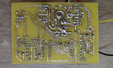
Figure 8.1: Custom Power Switching PCB
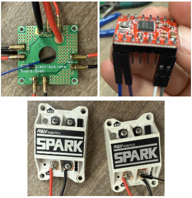
Figure 8.2.1-3: Power Distribution Board, Stepper Driver, Spark Motor Drivers
Last update we also talked about the start of soldering our custom remote controller together onto a protoboard, this time around we got to finish our final prototype design for the remote controller, Figure 8.3.2-3, to test the arm movement using the potentiometer encoders. We did however run into some issues with soldering, some of the pins were routed incorrectly so we had to make some design changes. We also added another encoder, not shown, for our fifth motor.
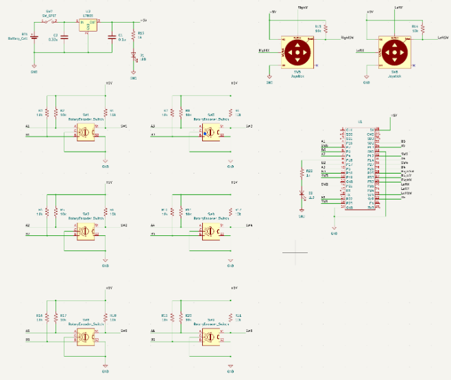
Figure 8.3.1: Remote Controller Schematics
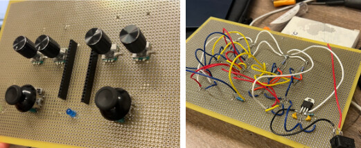
Figure 8.3.2-3: Front and Back of Prototype Remote Controller
Final Reflection
As we wrap up our project, we’re reflecting on how much we’ve grown. We are pleased that we successfully tested all the individual parts, even though our final goal of full system integration is still ahead.This project has been an invaluable learning experience; building components from scratch provided deeper insights and fostered strong teamwork as we integrated our contributions.
We’re excited to share that we’ll be continuing this project during the school year at Cal Poly Pomona. Our next steps are to complete the integration and then add autonomous movement using LiDAR and camera detection. We are very thankful for this internship opportunity with ROBOTIS and appreciate you following our progress.