I plan to build a robot using 12 XM430-W350-R servos (quadruped with 3 servos for each leg). I will use a 2400 mAh, 20C 3S LiPo battery. I was thinking of simply daisy chaining all of the servos, with one of the servos being connected to a U2D2 together with a U2D2 power hub. However, will the power reach all of the 12 servos sufficiently when wired this way, or do I need to add power to intermediate servos in the chain? If so, how could this be done in a good way?
You are correct in thinking that you would need to add additional power inputs to make sure all the servos receive adequate power, but given the description of your intended layout I think I can offer a more convenient solution.
If you add in a central hub board like this one to the center of your robot, you can give each leg it’s own dedicated daisy chain, and supply power to the entire robot through the inputs on the hub board.
I also wanted to ask why you are using a battery to power this platform, instead of SMPS input if you intend to use the U2D2? If you are intending to control this with a U2D2 you will require a tethered connection no matter what, so using an SMPS to supply power instead of an onboard battery will reduce the loaded weight of the robot.
Sorry, I wasn’t entirely clear about my plan. I’m not planning on using just a U2D2, but also a U2D2 power hub. I just saw that this has 3 4-pin RS-485 connections, could I then connect three of the legs to this power hub? Is there some way I could connect the fourth leg as well? Is there any alternative to the power hub board you sent that uses 4-pin connections instead (as the servos I use will have 4 pins), and what would the advantage of using this board be over using the U2D2 power hub?
I’m using a battery instead of SMPS because I want the robot to be mobile and not have to be close to a wall socket. I’m going to connect the U2D2 to a raspberry PI on the robot (which is powered by a separate battery).
It looks like that you’ll have to splice in two RS-485 cables into that last 4-pin connector on the U2D2 Power Hub.
In theory, ROBOTIS is going to release these types of “hubs”, but I don’t know when
You will have to splice two RS485 cables together to connect everything directly to the U2D2 PHB, but that’s probably the simplest way to connect everything together given what you are trying to set up.
I suggested the small board from Trossen specifically because it had enough ports to connect everything directly, but I didn’t realize that they don’t offer the board with RS485 connections.
Thanks for the answers! But how would I splice the cable exactly?
You will need two of those RS-485 DXL cables - let’s call them Cable A and Cable B:
-
For Cable A, cut all 4 wires about half-way between the two connectors.
-
For Cable B, cut all 4 wires as close as you can to one of the connectors, and you are going to use only the long section from now on. Ultimately, how you cut this cable depends on the physical location of the U2D2 Power Hub in relation to the 4 legs.
-
Splice the respective VDD and GND wires together as shown in picture below, using the usual solder and insulating tapes.
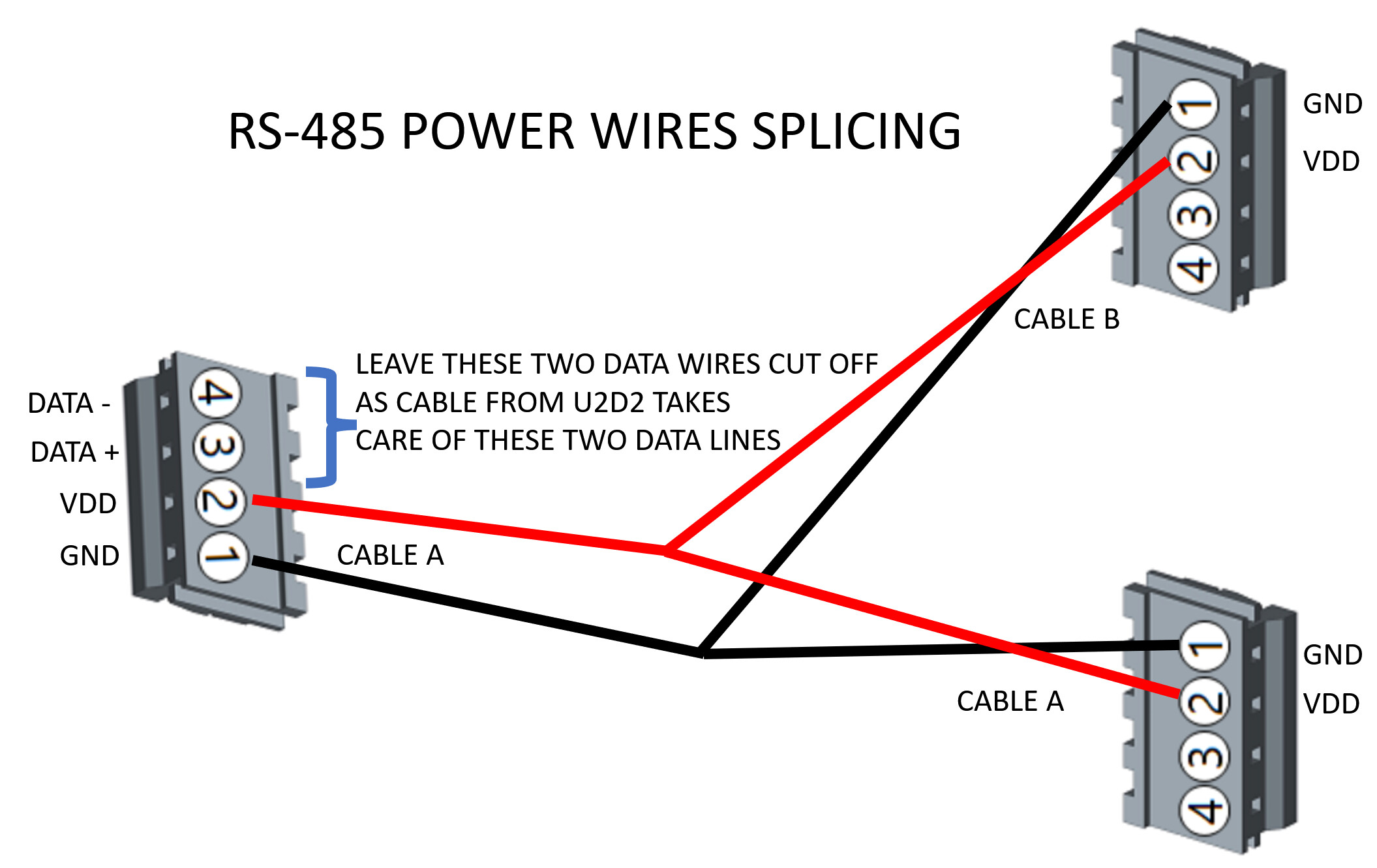
THE KEY will be to keep track of the specific VDD and GND PINs of the RS-485 connectors, so make sure that you mark them somehow before doing the splicing job.
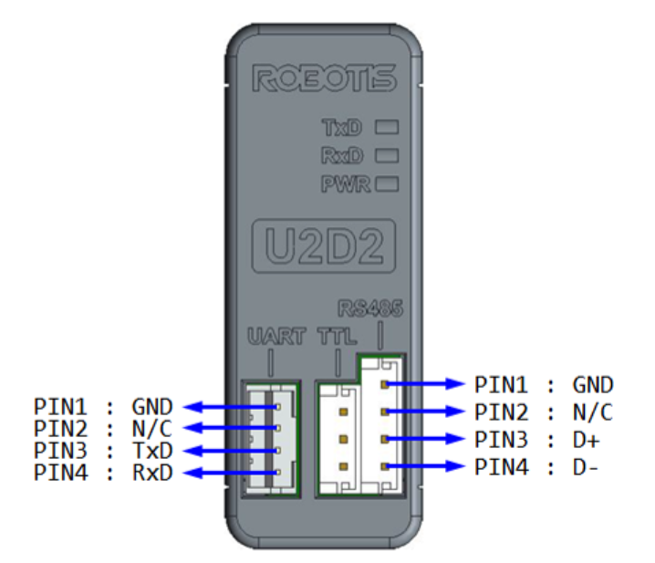
See this e-Manual link for more information
You do not need to splice the DATA+ and DATA- wires, because the “regular” RS-485 cable that you are going to use between the U2D2 and this DXL Network is taking care of the DXL-controlling aspects. Here you are just taking care of the Powering aspects for your DXLs.
Great, thanks for the answer! So basically, the daisy-chaining with the other dynamixels is what’s gonna transfer data to the servos, while the splicing will transfer power directly to these servos?
Yes, you got it! ![]()
![]()
You can use the same approach if you ever need to have a mixture of different DXLs that operate at different voltages, but still have control via a SINGLE Controller or U2D2.
Come to think of it, as the U2D2 has only ONE RS-485 connector, and so depending on how you wire all your DXLs together, physically, you may have to splice the DATA+ and DATA- wires also, just to make sure that you do have a true daisy-chain for the CONTROL circuit and as well as for the POWER circuit which happen to merge “mechanically” together at the U2D2 Power Hub, but “electrically” they remain separate, as the VDD line is not connected to the U2D2.
Good Luck with your project!