I have tested a proof of concept of driving a XL430 from the UART port of a RPi at 1Mbps.
The RPi has 2 UARTs: UART1 and mini UART. The mini UART isn’t stable at 1Mbps but the hardware of the UART1 is capable of much faster speeds than 1Mbps, the main limitation is the operating systems usage of the UART.
To get a stable 1Mbps from RPi UART I had to enable UART1 and increase the UART clock speed as the default clock speed is too low to generate UART at 1Mbps. I added the following 2 lines to the config.txt on RPi
init_uart_clock=16000000
enable_uart=1
Wiring:
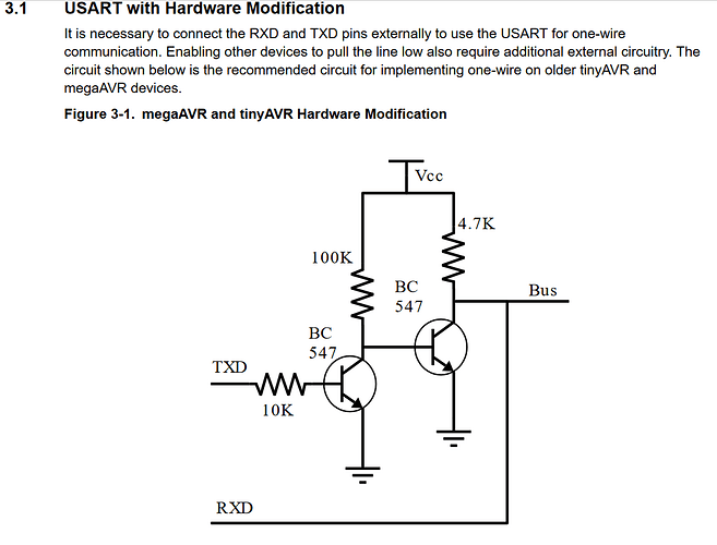
I connected the RX pin of the RPi directly to the data line. The TX pin of the RPi will idle high so I connected the TX pin through a 4.7k resistor so that it will act as a pull up on the data line so that it can drive the data line but when the dynamixel transmits the dynamixel can sink to low against the pull up of the TX pin of the RPi. . This seemed to work really nicely as a converter from UART full duplex to half duplex. I connected the positive and negative of my Lipo 3S battery and also connected a common ground from the Lipo negative to the GND pin of the RPi.
I downloaded and installed the DynamixelSDK from Robotis github. I changed the baud rate to 1mbps and the port to the UART in read_write.py and ran the test script to test that the RPi could both transmit and receive to the dynamixel.
see https://www.youtube.com/watch?v=7tzznz7f3sU
3 Likes
@roboteer
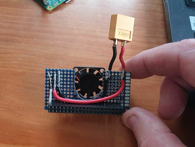
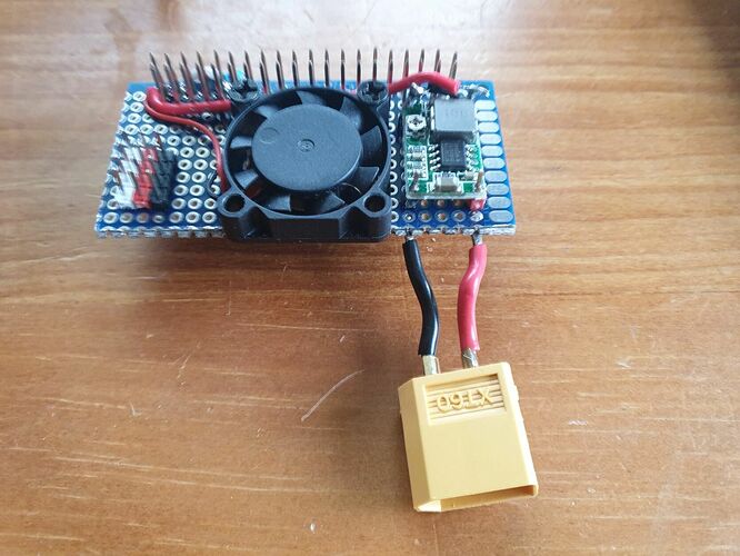
I have made up a prototype board on some perf board. It has the same circuits fro the dynamixel but I have added a fan for the RPi zero2’s CPU and a voltage regulator to step down the battery voltage to 5v to supply the 5v rail of the RPi so it can be powered of the same battery as the Dynamixels as well as stackable header so other hats can be added on top.
2 Likes
Here it is in action Standalone - YouTube
@Out_of_the_BOTS
Super Cool!
Essentially, you created your own custom Dynamixel HAT for the RPi system. Thanks for sharing the detailed pictures showing how to put this HAT together. When you get the chance, can you share your BOM for this project?
Also, can you try to run the example “sync_read_write.py” with two XL-430s? This example has lots of DXL packets going back and forth in the DXL network. I am interested to see if your system can maintain no loss of DXL packets at run time. Previously, I was getting random packet losses at baud rates more than 115.2 Kbps in Python (but not in compiled C++) on the RPi4B.
@roboteer
re lost packets on RPi. With lots of googling and reading what other have done I have some understanding to the limitations of RPi UARTs. The RPi has 2 UARTs, usually the Bluetooth is attached to UART1 so make sure u have either moved the Bluetooth to mini UART or disabled the Bluetooth (I disabled the Bluetooth myself in config.txt).
The RPi UART hardware is capable of speeds up to 45Mbps but the operating system is the limitation. The OS standard setup runs the UART clock source to slow for reliable communications above speeds of 115200 but in the config.txt you add the line init_uart_clock=16000000 to increase the UART clock so it will be stable at 1Mbps.
The current HAT that I made is a bit of a prototype and I already have some ideas to improve it like using sideways mount JST EH so that the cables come out the side rather than up so that you can stack more HATs on top easy, I think that I will also add a 1000uf cap to the battery input because if you add lots of dynamixels moving all at once then you can get drops in voltage.
I think that I am going to draw up a PCB design and get if made up as this HAT and a RPi zero 2 could be a great combo for my robotic projects. The RPi zero 2 has the same processor as the RPi3 and RPi3 b+ but with the RAM mounted on top. Thermal dissipation governs how fast you can run the processor at, RPi3 ran at 1.2GHz but with RPi3 b+ they had a better packing of the CPU that got better heat dissipation so they ran it at 1.4GHz. The RPi zero 2 has the worst heat dissipation because the RAM is on top on the CPU and the zero form factor means less PCB to pull heat away. Lots of people have done a lot of testing with increasing RPi zero 2 speed and with a heat sink and fan everyone got very stable operation without over heating at 1.3GHz, this would put the processing performance of a RPi zero2 with fan and heat sink between a stock standard RPi3 and RPi3b+
@Out_of_the_BOTS
Thanks for the details regarding RPi UART config settings, but I am still puzzled why using “compiled C++” worked OK for me though, while using Python3 failed for me, as I kept the UART configuration settings at their default values for both situations. And the Python code reported that it managed to change the baud rate OK to 1 Mbps, and the “sync_read_write.py” program worked most of the time, but it just had random packet losses, while the compiled C++ version never did. I’ll need to try that setting init_uart_clock=16000000 next to see if I get better performance out my Python programs.
@roboteer
OK that is strange.
Python is an interrupter that calls the under lying compiled C object.
The C library that you used to operate the UART would have to be telling the OS to change the UART clock source to be able to send/recive stable UART packets at higher speeds.
Either way it is the operating system that actually does the sending and receiving from the UART peripheral. The code python or C when sending just says to the OS here’s buffer of bytes can you sent it for me and when receiving from the UART the OS is constantly receiving and placing anything it receives in to a buffer and when you code want to receive it just asks the OS do you have anything already in your receive buffer for me.
@Out_of_the_BOTS can I just confirm the you’re using the 3V3 logic level of the Pi to communicate with the motors? The dual buffer circuit that ROBOTIS recommend pulls the bus up to 5V so I just wanted to check.
I did use 3.3v and it worked but if I am using longer cables or if there is capacitance in my board then it can get dropped packets. I suggest using a level shifter to converter between the 3.3v and 5v and also a level shifter on the RX pin as the dynamixel sends back 5v level and I think this will break the RPi after awhile.
1 Like
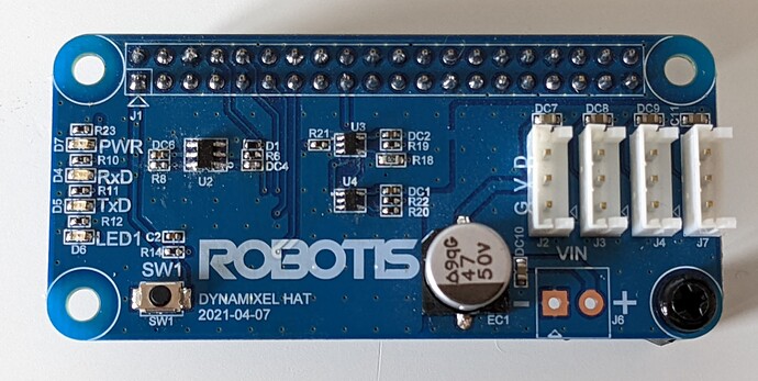
Thanks @Out_of_the_BOTS! ROBOTiS had a limited run of this
Dynamixel HAT that contains an auto switching half duplex buffer. I asked but they wouldn’t give me the schematic and i haven’t been able to work out how it works. U3 and U4 in the picture are the standard half to full duplex buffer but the chip enables are being driven from U2 which is maybe an inverter? All I can read on it is H14 and I guess it’s a SOT23
1 Like
@rosterloh
In the end if Robotis is manufacturing what you need then this saves you designing and manufacturing your own.
If you need to incorporate it in to our own PCB then I would suggest buying 1 of these boards and following the traces and reading the IC numbers and reverse engineer it as it is a pretty simple circuit. I assume the little ICs are level shifters as the dynamixels use 5v data line and RPi uses a 3.3v data line
I am going to see if that I can buy 1 of these HAT myself as they look pretty handy. Also do you know if they will work on a Jeston boards?? As if I can actully manage to buy a Jeston board I want to use it for a robot that uses AI computer vision.
I would change the header to a through stack-able header so that I can still use the rest of the RPi pins.
The other suggestion that I would make to Robotis that they can improve on in next generation is adding a really small fan as the main problem with RPi zero 2 is it has over heating problems so they clocked the CPU down. If you have a fan and really samll heat sink then you can run the CPU at same speeds as the RPi3 b+ as it has the same CPU as RPi3 b+
@Out_of_the_BOTS
As far as I know ROBOTIS don’t sell this board. They sent a limited run out to beta testers and I requested if they had any spare left over and they sent me one. I’d suggest this is the only way you’d be able to get this to work with a Jetson (I’ve only tried a Nano) because the drive strength of the gpios is so low (1mA) that I couldn’t do anything useful with them.
From my tracing it looks like U2 is an inverting Schmitt trigger with input connected to TX from the Pi who’s output drives the enable of RX buffer (U4) and not enable of TX buffer (U3)
@rosterloh
I am studying at university atm as well as running a business so don’t have much time but at some point I would like to design a good RPi HAT to drive dynamixels that also has a buck converter to power the RPi and a fan to cool it.
This is the best circut that I have seen for converting from full duplex to half duplex. It would also need a level shifter on the RX pin to conveter the 5v on the bus line to 3.3v
Hi,
Have you had any connection problems over time?
I’ve made a similar setup using an opencm 9.04 connected to a pi zero. Data transmission works fine for 10-20 seconds and after this it just stops responding…
My setup and code is still a work in progress so the problem probably is on my side but I was just wondering if you’ve been able to keep the data connection running for a long period of time.
Kind regards,
Benoît Lagasse
I haven’t had a problem myself.
What can quite often happen is the buffer that stores the UART I/O overflows.
If your sending data quicker than the receiver is reading it then in UART input buffer on the reciver side will over flow
2 Likes
Hi,
Thanks for the quick response! I will keep that in mind and hope I it will work better once my code is a bit cleaner 


