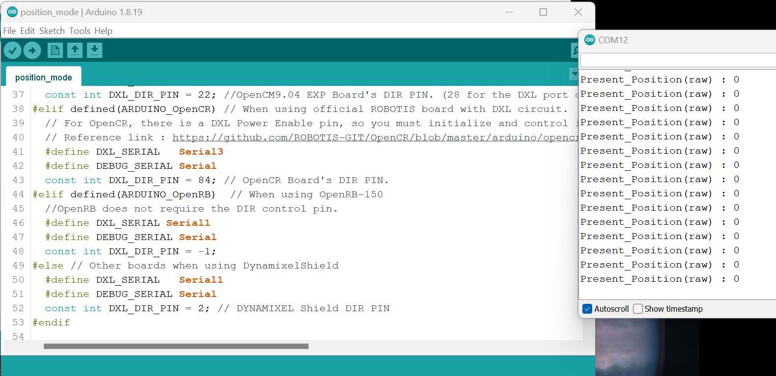
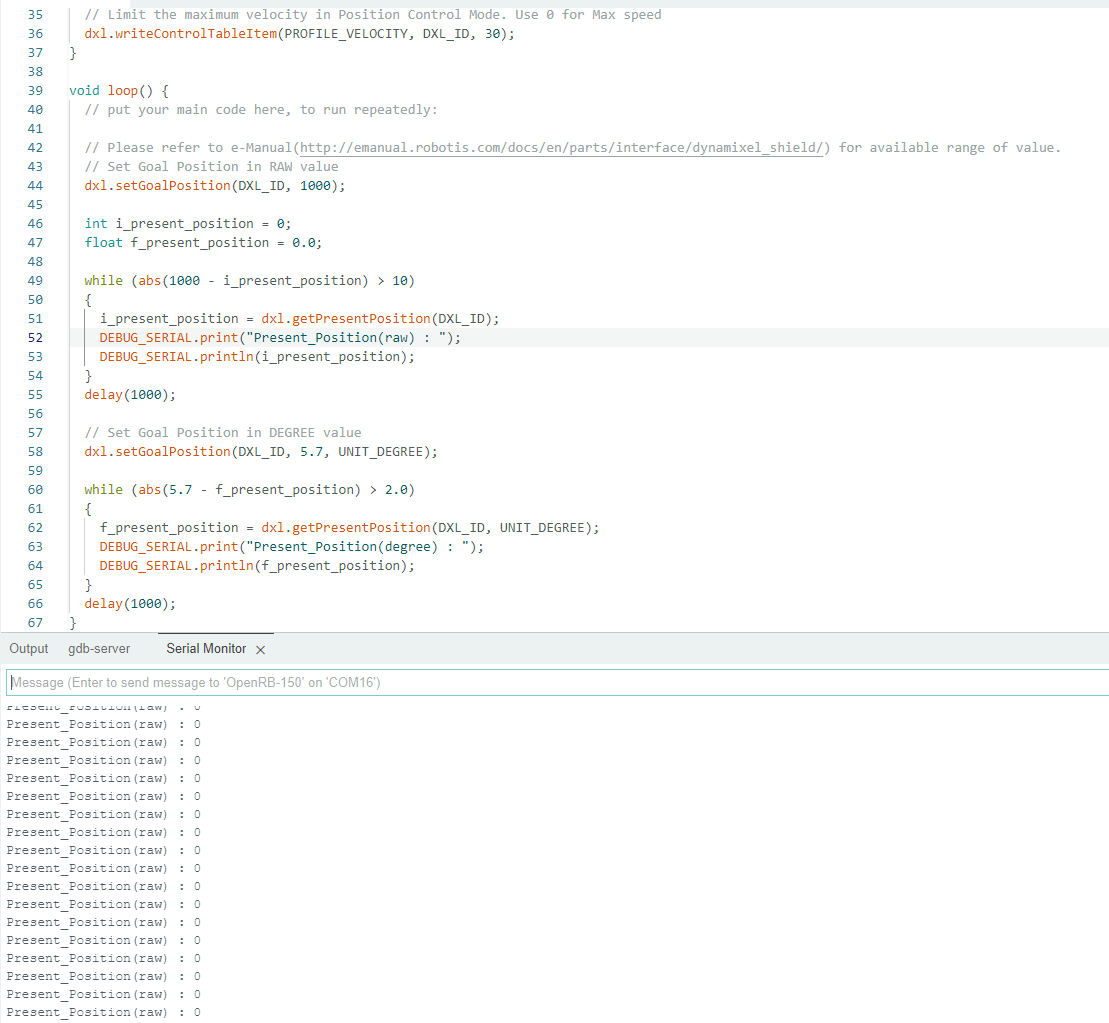
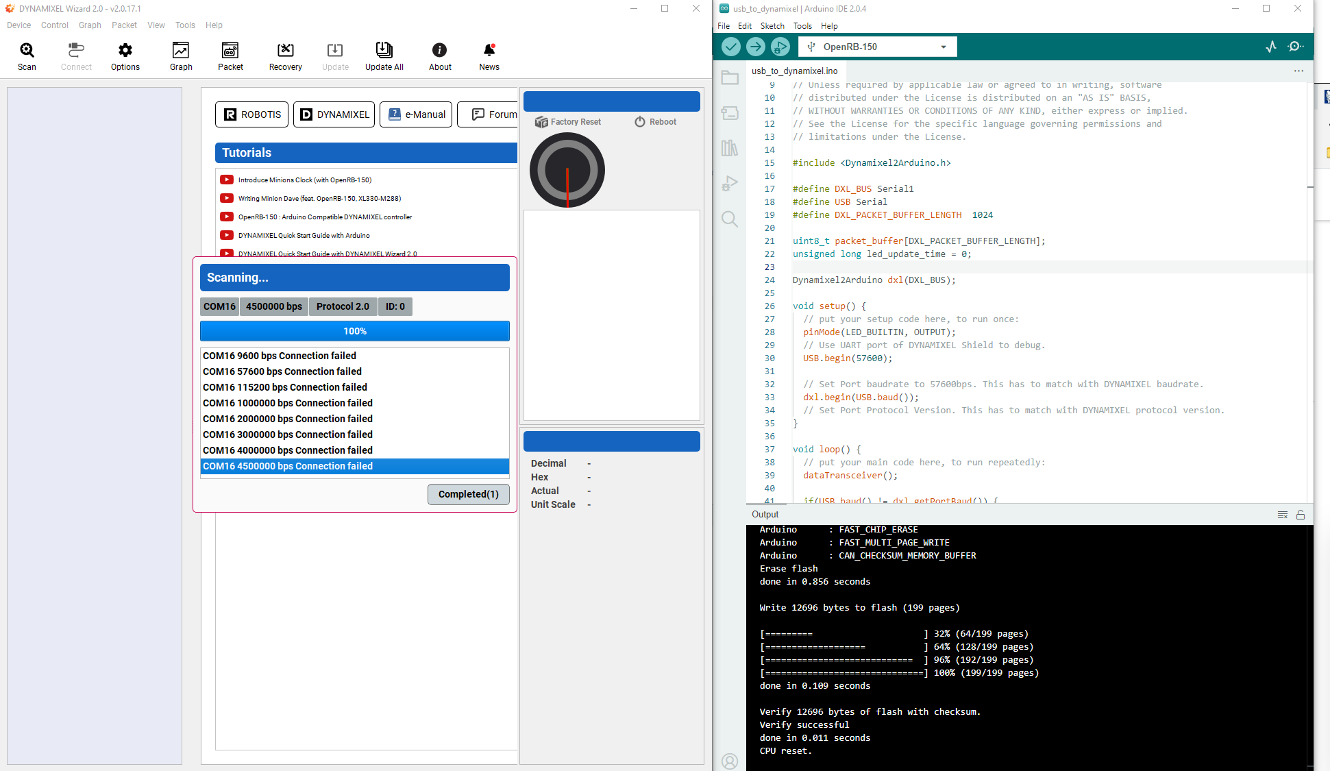
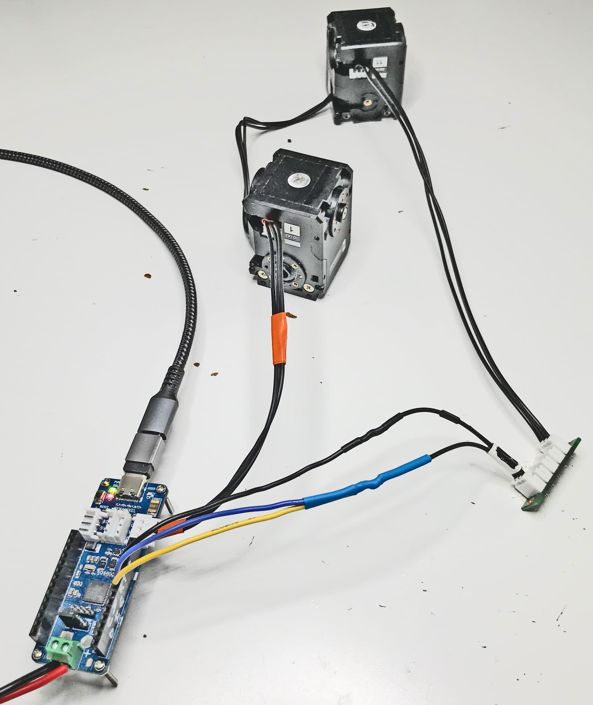
Thanks for your response, however following you advice I uploaded the example position_control sketch. This one didn’t run either
/*******************************************************************************
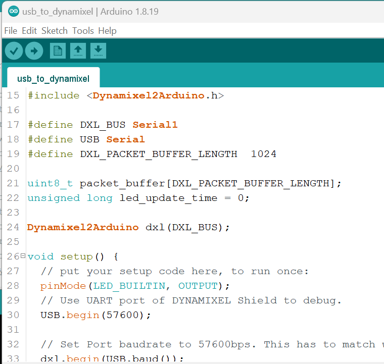
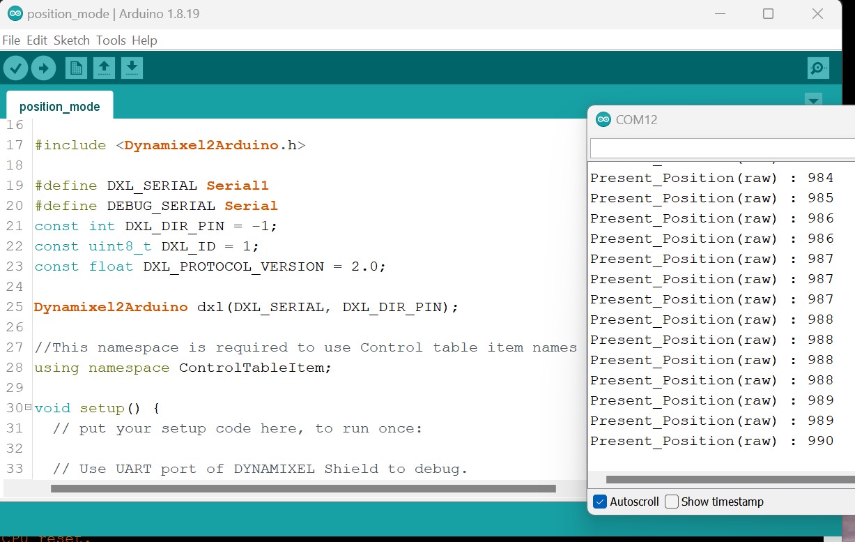
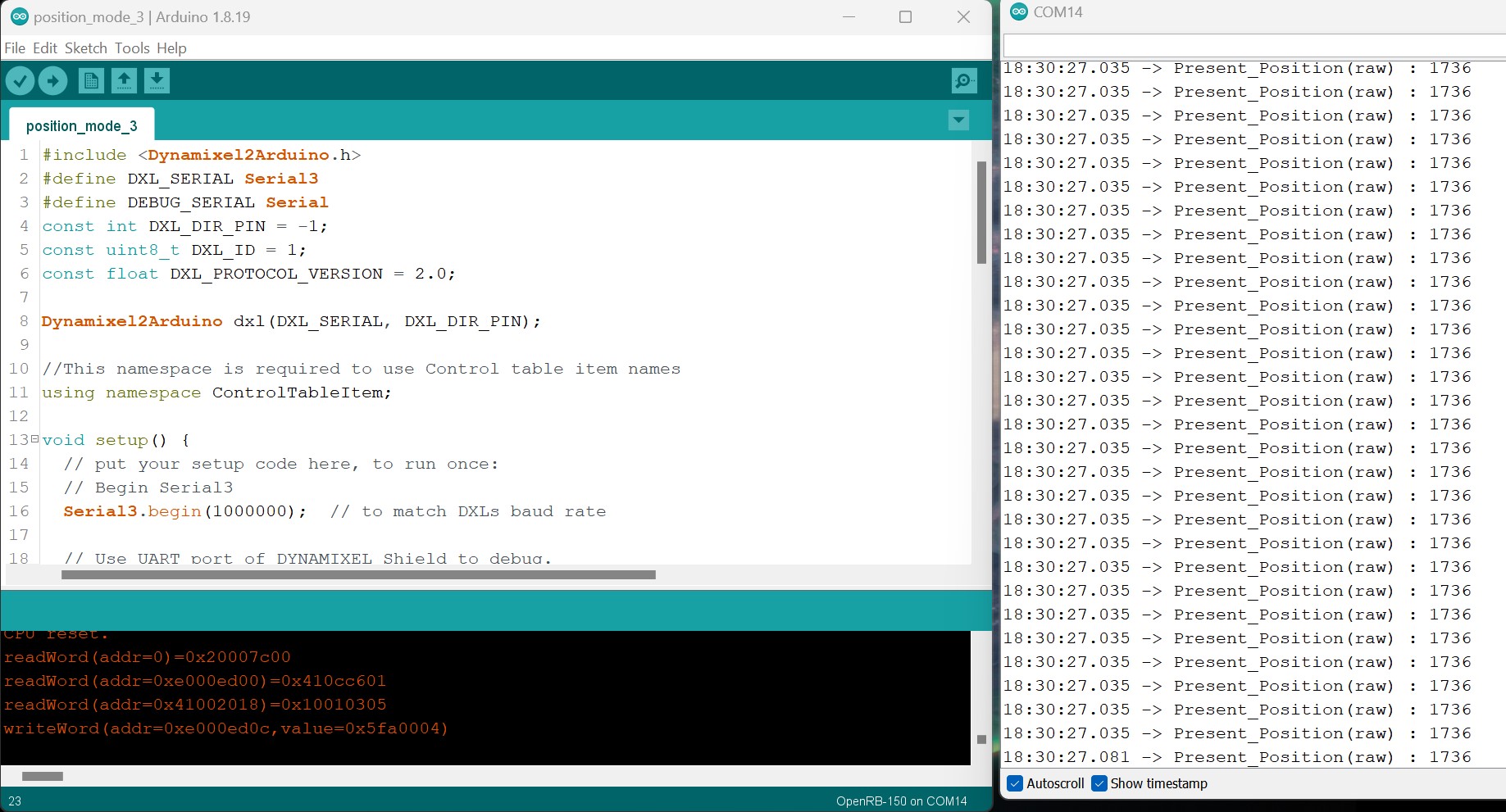
#include <Dynamixel2Arduino.h>
// Please modify it to suit your hardware.
#if defined(ARDUINO_AVR_UNO) || defined(ARDUINO_AVR_MEGA2560) // When using DynamixelShield
#include <SoftwareSerial.h>
SoftwareSerial soft_serial(7, 8); // DYNAMIXELShield UART RX/TX
#define DXL_SERIAL Serial
#define DEBUG_SERIAL soft_serial
const int DXL_DIR_PIN = 2; // DYNAMIXEL Shield DIR PIN
#elif defined(ARDUINO_SAM_DUE) // When using DynamixelShield
#define DXL_SERIAL Serial
#define DEBUG_SERIAL SerialUSB
const int DXL_DIR_PIN = 2; // DYNAMIXEL Shield DIR PIN
#elif defined(ARDUINO_SAM_ZERO) // When using DynamixelShield
#define DXL_SERIAL Serial1
#define DEBUG_SERIAL SerialUSB
const int DXL_DIR_PIN = 2; // DYNAMIXEL Shield DIR PIN
#elif defined(ARDUINO_OpenCM904) // When using official ROBOTIS board with DXL circuit.
#define DXL_SERIAL Serial3 //OpenCM9.04 EXP Board’s DXL port Serial. (Serial1 for the DXL port on the OpenCM 9.04 board)
#define DEBUG_SERIAL Serial
const int DXL_DIR_PIN = 22; //OpenCM9.04 EXP Board’s DIR PIN. (28 for the DXL port on the OpenCM 9.04 board)
#elif defined(ARDUINO_OpenCR) // When using official ROBOTIS board with DXL circuit.
// For OpenCR, there is a DXL Power Enable pin, so you must initialize and control it.
// Reference link : OpenCR/port_handler_arduino.cpp at master · ROBOTIS-GIT/OpenCR · GitHub
#define DXL_SERIAL Serial3
#define DEBUG_SERIAL Serial
const int DXL_DIR_PIN = 84; // OpenCR Board’s DIR PIN.
#elif defined(ARDUINO_OpenRB) // When using OpenRB-150
//OpenRB does not require the DIR control pin.
#define DXL_SERIAL Serial1
#define DEBUG_SERIAL Serial
const int DXL_DIR_PIN = -1;
#else // Other boards when using DynamixelShield
#define DXL_SERIAL Serial1
#define DEBUG_SERIAL Serial
const int DXL_DIR_PIN = 2; // DYNAMIXEL Shield DIR PIN
#endif
const uint8_t DXL_ID = 1;
const float DXL_PROTOCOL_VERSION = 2.0;
Dynamixel2Arduino dxl(DXL_SERIAL, DXL_DIR_PIN);
//This namespace is required to use Control table item names
using namespace ControlTableItem;
void setup() {
// put your setup code here, to run once:
// Use UART port of DYNAMIXEL Shield to debug.
DEBUG_SERIAL.begin(115200);
while(!DEBUG_SERIAL);
// Set Port baudrate to 57600bps. This has to match with DYNAMIXEL baudrate.
dxl.begin(57600);
// Set Port Protocol Version. This has to match with DYNAMIXEL protocol version.
dxl.setPortProtocolVersion(DXL_PROTOCOL_VERSION);
// Get DYNAMIXEL information
dxl.ping(DXL_ID);
// Turn off torque when configuring items in EEPROM area
dxl.torqueOff(DXL_ID);
dxl.setOperatingMode(DXL_ID, OP_POSITION);
dxl.torqueOn(DXL_ID);
// Limit the maximum velocity in Position Control Mode. Use 0 for Max speed
dxl.writeControlTableItem(PROFILE_VELOCITY, DXL_ID, 30);
}
void loop() {
// put your main code here, to run repeatedly:
// Please refer to e-Manual(DYNAMIXEL Shield) for available range of value.
// Set Goal Position in RAW value
dxl.setGoalPosition(DXL_ID, 1000);
int i_present_position = 0;
float f_present_position = 0.0;
while (abs(1000 - i_present_position) > 10)
{
i_present_position = dxl.getPresentPosition(DXL_ID);
DEBUG_SERIAL.print("Present_Position(raw) : ");
DEBUG_SERIAL.println(i_present_position);
}
delay(1000);
// Set Goal Position in DEGREE value
dxl.setGoalPosition(DXL_ID, 5.7, UNIT_DEGREE);
while (abs(5.7 - f_present_position) > 2.0)
{
f_present_position = dxl.getPresentPosition(DXL_ID, UNIT_DEGREE);
DEBUG_SERIAL.print("Present_Position(degree) : ");
DEBUG_SERIAL.println(f_present_position);
}
delay(1000);
}